


20
ENGLISH
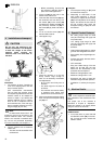
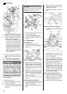
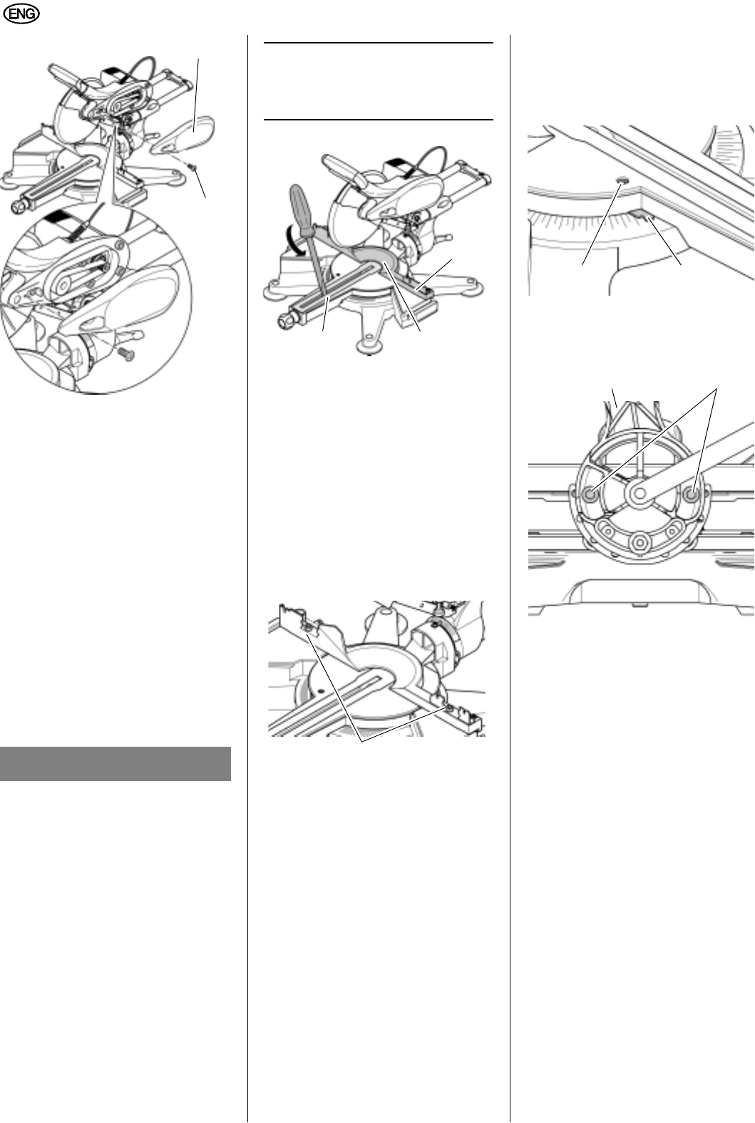
2. Check the drive belt with your
thumb. If the drive belt needs to be
tightened (more than 1/8" play) or if
it needs to be replaced because of
visible wear, tear or cracking:
Loosen the four metric Allen head
screws by turning each screw
about one turn counterclockwise.
Replace the belt if necessary or
just tighten it by sliding the motor
to the rear until the belt is tight.
Hold the motor in its position and
tighten all four screws by turning
them clockwise until they are
securely tightened.
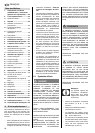
3. Replace the plastic cover (67) and
secure with the Phillips head screw
(68).
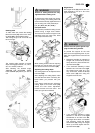
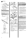
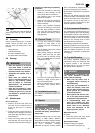
9.3 Kerf Plate Replacement
To replace the kerf plate:
1. Swing the hinged fence down (69).
2. Take the fence (70) off.
3. Loosen the kerf plate (71) by prying
it loose with a screwdriver and then
remove it.
3
Note:
This will destroy the kerf plate
(71). Once removed from the machine, a
kerf plate must never be re-used.
4. Insert the new kerf plate, making
sure it snaps into place.
5. Install the fence (70) and adjust it.
6. Swing the hinged fence (69) up and
secure it.
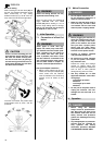
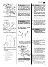
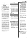
9.4 Adjustments
Fence adjustment
1. Swing the hinged fence down.
2. Loosen the fastening screws (72) of
the fence.
3. Adjust the fence position with a con-
tractor's square or another appropri-
ate right angle until it is exactly per-
pendicular (90
°) to the saw blade
with the rotating table locked in the
0° position.
4. Tighten the metric Allen head set
screws on the the fence and then
use the square to check your adjust-
ment. If necessary, re
peat the
adjustment procedure.
5. Swing the hinged fence up and
secure it.
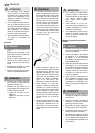
Miter angle indicator adjustment
1. Turn the rotating table to one of the
preset stops at the °0, 15°, 22.5°,
30°, 45°, or 60°positions.
2. Loosen the metric Allen head scre
w
(73).
3. Adjust the position of the indicator
(74) until it points exactly to the cor-
responding angle value.
4. Tighten the metric Allen head screw
(73).
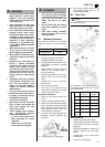
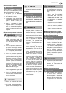
Bevel tilt positive stop adjustment
1. Lock the track arm holder (75) in the
0° position.
2.
Loosen the two metric Allen head
screws (76) at the back of the
machine by turning them about one
turn counterclockwise.
3. Use a contractor’s square or
another appropriate right angle and
adjust the track arm
holder until the
saw blade is exactly perpendicular
(90°) to the the rotating table.
4. Tighten the two metric Allen head
screws (76) at the back of the
machine by turning the screws (76)
clockwise until the
angle setting is
secured. Check your adjustment
with the square. If necessary, repeat
the adjustment procedure.
Miter angle indicator adjustment
1. Loosen the Phillips head screw (78).
2. Adjust the position of the indicator
(77) until it points exactly to the cor-
res
ponding angle value, e.g. 0°.
3. Tighten the Phillips head screw (78).
A DANGER
If the kerf plate is damaged, small
parts may become stuck between
kerf plate and the saw blade and
cause the saw blade to jam. Check
the machine for possible damage
before every use. Replace a dam-
aged kerf plate immediately! Use
only OEM parts! Non-OEM parts and/
or parts not specifically approved by
the manufacturer may lead to unfore-
seen damage and possibly result in
personal injuries.
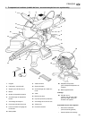
67
68
69
70
71
72
73 74
75 76