


14 - 2
CROSS COMPENSATION / SETTING OF RESPSONSE TIME (TC ONLY)
ETC00781(4) Series 100 e 02/2004
14.1.1 Preparing Actions
The adjustment procedure for alteration the factory settings of cross compensation is as
follows:
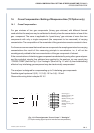
The number of interfering gases and the type of analog input signal is selected by configuring
solder bridges on the printed circuit boards “WAP 100” (TC signal processing) and “BSE 01”
(analog input signals).
P Open the analyzer housing (cf. Section 23).
P Remove the PCB´s and check and / or alter the solder bridges (cf. table 14-1).
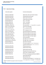
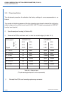
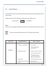
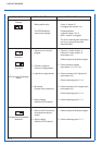
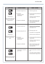
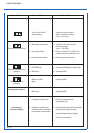
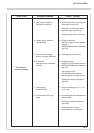
CROSS COMPENSATION
Table 14-1: Solder bridges
(TC option analog signal inputs for cross compensation)
Analog Input PCB WAP 100 PCB BSE 01
1 LB 9 LB 8 LB 1 LB 9
2 LB 6 LB 7 LB 2 LB 6
Signal 3 LB 13 LB 12 LB 3 LB 12
0 - 1 V DC 1-2 open open closed
0 - 10 V DC 1-2 open open open
0 - 20 mA 1-2 open closed closed
0.2 - 1 V DC 2-3 closed open closed
2 - 10 V DC 2-3 closed open open
4 - 20 mA 2-3 closed closed closed
not used open open open open
Number
P Reinstall the PCB´s and correctly replace any connector.