


14 - 3
CROSS COMPENSATION / SETTING OF RESPSONSE TIME (TC ONLY)
ETC00781(4) Series 100 e 02/2004
14.1.2 Adjustment Procedure
P Switch on the TC analyzer (chapter 6.) and all analyzers used for measuring interfering
gas components.
P Perform zeroing and spanning of all relevant measuring channels.
P Connect the gas paths of all analyzers in series and purge with zero gas (N
2
, nitrogen).
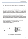
P Connect the analog signals of the analyzers used for measureing interfering gas
components to the respective analog input (Fig. 14-1) of the TC analyzer.
The following steps have to be executed for each interfering gas seperately.
P Supply the maximum concentration of the respective interfering gas (maximum
concentration should be full-scale of the analyzer measuring the interfering gas).
For external analyzers with different measuring ranges be sure that the analog signal
connected to the TC analyzer is related to the highest measuring range and that
this measuring range does not change while adjusting the cross compensation.
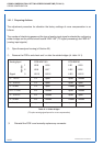
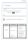
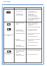
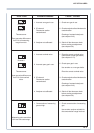
P Adjust the correlated potentiometers of the PCB “WAP 100” to set the analog signal output
of TC measurement to “Zero”.
The potentiometer assignments is as follows:
Interfering gas / analog input 1: Q 1 (R 71)
Interfering gas / analog input 2: Q 2 (R 84)
Interfering gas / analog input 3: Q 3 (R 118)
P Purge with zero gas (N
2
, nitrogen), check the zero point and start a zero calibration via
keypad again if necessary.
Supply the maximum concentration of the respective interfering gas again and perform
a fine setting of zero-point using the corrrelated potentiometers of PCB “WAP 100”.
When the adjustment has been finished
P Close the analyzer housing (cf. Section 23).
CROSS COMPENSATION