


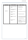


PLUG PIN ALLOCATION OF PRINTED CIRCUIT BOARDS
18 - 1
ETC00781(1) Series 100 e 10/2001
Rosemount Analytical
Front panel
X 16
X 18
X 1
17
8
P1
P2
X 9
1
X 3
14
X 2
1
1
1
X 5
1
X 6
J 9
1
X 7
MarkedMarked
X 36
EPROM
(at BAF 01)
Option
BAF 01
P 1
EPROM
(D 30 at BKS)
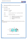
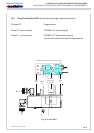
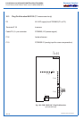
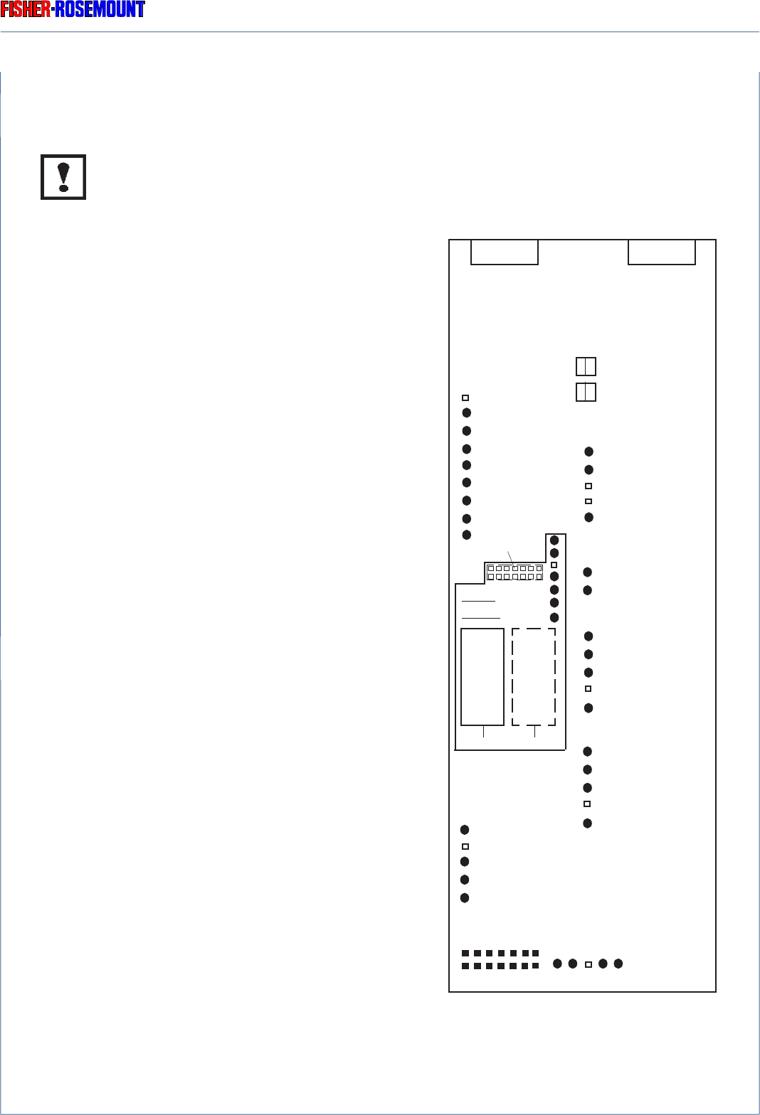
18. Plug Pin Allocation of Printed Circuit Boards
Be sure to observe the safety measures !
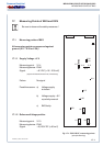
18.1 Plug Pin Allocation of BKS
P 1 or P2 24 V DC supply to
optional internal consumer
(heater of paramagn. O
2
sensor e.g.)
X 1 Front panel BXF (P8)
X 16 Digital Outputs, parallel
X 18 Analog Outputs
J 9 Option BSI 10:
Status signals and
serial interface resp.
X 36/ Option BAF 01:
D 30 Pressure sensor PCB
P 1 at Option BAF 01:
Connector for pressure sensor
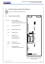
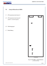
PLUG PIN ALLOCATION OF BKS
Fig. 18-1: PCB “BKS”, Plug Pin Allocation
(principle drawing)