


REPLACEMENT AND CLEANING OF PHOTOMETRIC COMPONENTS
24 - 8
ETC00781(4) Series 100 e 02/2004
24.6.2 Sealed Photometer (Option)
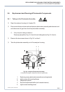
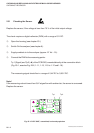
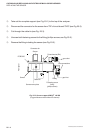
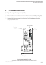
P Slightly loosen the light source mounting screws (shown in Fig. 24-1 as Item 5) or the
temperature sensor (shown in Fig. 24-1 as Item 3) resp. for channel 1 or channel 2.
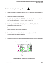
P Set the zero level precisely to 0 V (± 100 mV) by turning the corresponding light source.
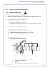
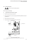
P For photometer with pyroelectrical detector only:
To enable physical zero level adjustment, one out of three different fix apertures
(zero level adjustment aperture) are installed inside the light source.
For simple replacement the aperture is fixed inside the source with a magnet.
If turning the light source is not sufficient, use another fix aperture (zero level
adjustment aperture; see item 24-2) and again turn the light source.
P Tighten the light source mounting screws (shown in Fig. 24-1 as Item 5) or the
temperature sensor (shown in Fig. 24-1 as Item 3) resp. for channel 1 or channel 2.
When the physical zeroing has been set correctly, perform an electrical zeroing (see chapter
9.).
PHYSICAL ZEROING