


CHECKING AND REPLACING AN ELECTROCHEMICAL OXYGEN SENSOR
25 - 6
ETC00781(4) Series 100 e 02/2004
25.2.2 Removing the Sensor
P Take the consumed sensor out of the fitting.
P Take off the stopper from new sensor and place the new sensor into the fitting, so
that the name plate is at the top of the sensor.
P Close the consumed sensor with the stopper and send it back to our factory.
25.2.3 Reinstalling the Sensor
a) Oxygen Measurement without IR - channel
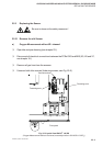
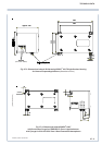
P Put the fitting with the (new) sensor onto the support, move to the stop and screw with
the two fastening screws (phillips screws, see Fig. 25-3)
P Fix the sensor with a cable tie to the support (see Fig. 25-3).
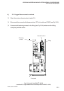
P Connect the connector for the sensor to “P2” of circuit board “OXS” (see Fig. 25-5 / chapter 18.).
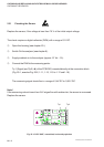
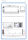
P Insert the complete support (see Fig. 25-3) into the analyzer and fix it with the two
allen screws (fastening screws, see Fig. 25-2).
P Reconnect all gas lines to the fittings (see Fig. 25-2 and Fig. 25-3).
Do not interchange gas inlets and gas outlets.
P Reconnect all electrical connections between OXS and BKS (X5 and X7, see chapter 18.).
P Perform a leakage test (see chapter 22.) and set the sensor (see chapter 25.2.4).
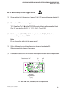
b) Combined IR / Oxygen Measurement
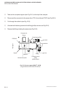
P Put the fitting with the (new) sensor onto the support, move to the stop and fix it with
the two fastening screws (see Fig. 25-4)
P Connect the connector for the sensor to “P2” of circuit board “OXS” (see Fig. 25-5 / chapter 18.).
P Perform a leakage test (see chapter 22.) and set the sensor (see chapter 25.2.4).
REPLACE / REINSTALL THE SENSOR