


22 - 1
LEAK TESTING
ETC00781(4) Series 100 e 02/2004
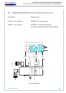
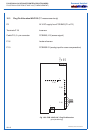
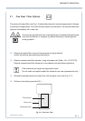
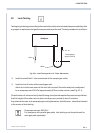
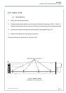
Fig. 22-1: Leak Testing with an U - Tube - Manometer
P Install a waterfilled U - tube manometer at the sample gas outlet;
P Install a shut-off valve at the sample gas inlet.
Admit air into the instrument at the shut-off valve until the entire analyzer is subjected
to an overpressure of 50 hPa (approximately 500 mm water column; see Fig. 22-1).
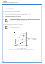
Close the shut-off valve and verify that following a brief period required for pressure equilibrium,
that the height of the water column does not drop over a period of about 5 minutes.
Any external devices, such as sample gas cooling hardware, dust filters etc., should be checked
in the course of leak testing.
Overpressure max. 500 hPa !
For analyzers with parallel gas paths leak testing must be performed for
each gas path separately !
22. Leak Testing
Testing for gas leakage should be performed at bimonthly intervals and always immediately after
any repair or replacement of gasline components is performed. The test procedure is as follows:
Analyzer
Overpressure
approx. 50 hPa
Valve
Water