


page 106 008-0608-00
12.3 Excitation and Signal Jumpers
12.3.1 Overview
The High-Level Input channel has hardware jumpers which allows configuration of
excitation supply voltages and signal inputs to match the wide variety of amplified
pressure, load and DC-DC LVDT transducers.
12.3.2 Setting Jumpers
Step 1: Find the “Case Removal” section in Chapter 4 “Chassis Models” on page 25
that matches the particular chassis model. Follow the directions and remove
the rear panel.
Step 2: Remove the channel board from the chassis.
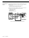
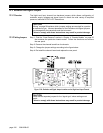
Step 3: Change the jumper settings according to the figure below.
Step 4: Re-install the channel board and replace the rear panel.
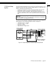
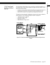
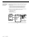
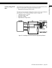
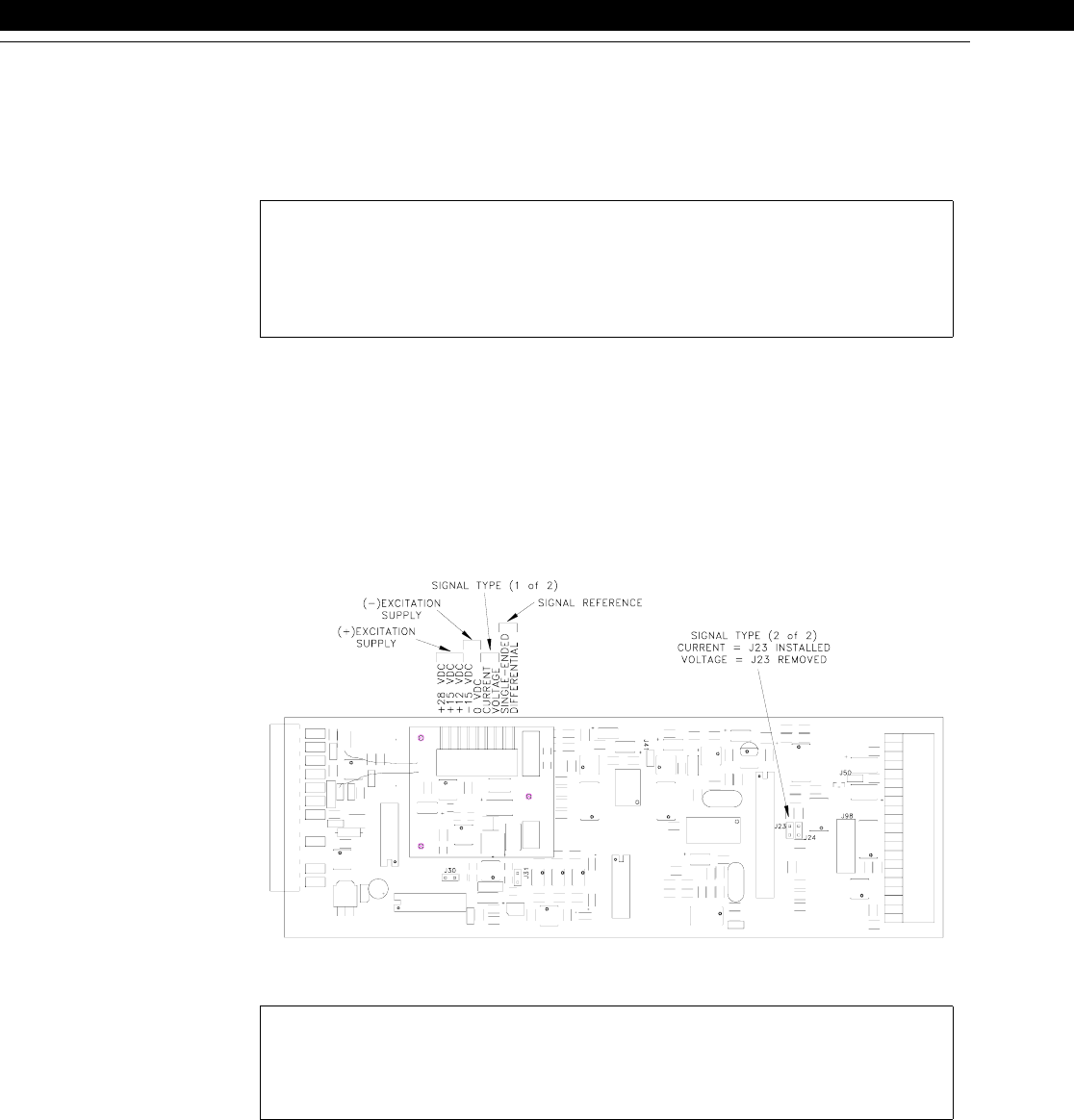
Figure 12-8: Excitation and Signal Jumper Locations on the High-Level Input Channel
CAUTION
“Wiring” on page 98 explains which jumpers settings are required for a particu-
lar transducer type. Incorrect placement of the Excitation and Signal jumpers
can damage both the transducer and the instrument.
Failure to comply with these instructions may result in product damage.
CAUTION
There are two separate jumpers for the “signal type” whose settings must
match.
Failure to comply with these instructions may result in product damage.