


SC Series Instruction Manual page 133
DAC Output Channel14
14.5 Channel Menu
Each DAC Output channel is configured and calibrated via its channel menu.
Detailed instructions on operating the instrument in the SETUP Menu mode can
be found in “SETUP Menu mode” on page 23. A diagram of all menus is located
in “Setup Menu Reference” on page 157.
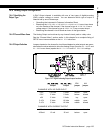
14.5.1
DAC SETUP
Sub-Menu
This sub-menu contains four items that controls the analog output of the channel.
DAC. CHANNEL
Menu Item
This chooses which channel will drive the Digital-to-Analog Converter (DAC) out-
put.
DAC. SOURCE
Menu Item
This designates the data source of the channel monitored by the analog output.
Each channel has three data sources: the live tracking value (TRACK), its highest
value (PEAK), and its lowest value (VALLEY).
The options for this menu item are:
•“
TRACK
” means the live tracking value of the channel.
•“
PEAK
” means the highest value of the channel since the peak/valley detector
was last cleared.
•“
VALLEY
” means the lowest value of the channel since the peak/valley detector
was last cleared.
DAC. ZERO-SCALE
Menu Item
This specifies what value, in engineering units, corresponds to zero output on the
Analog Output.
“Zero output” might be 0 Volts, 2.5 Volts, 5 Volts, 4 mA or 12 mA depending on if
the channel has a voltage or current output and how it is configured. See the
“Digital-to-Analog Output” section of this chapter for details.
This menu item is not automatically updated by another channel’s Signature Mod-
ule equipped transducer.
DAC. FULL-SCALE
Menu Item
This specifies what value, in engineering units, corresponds to full output on the
Analog Output.
“Full output” might be 5 Volts, 10 Volts or 20 mA depending on if the channel has
a voltage or current output and how it is configured. See the “Digital-to-Analog
Output” section of this chapter for details.
This menu item is not automatically updated by another channel’s Signature Mod-
ule equipped transducer.