


SC Series Instruction Manual page 95
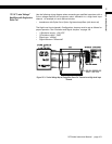
AC/AC-LVDT Input Channel11
11.8 Troubleshooting
11.8.1 Error Messages
See “Error Messages” on page 151 for information relating to error messages.
11.8.2 Common
Problems and Solutions
Erratic Display
Check electrical connections for continuity and the transducer’s wiring code from its
Certificate of Calibration.
Make sure that the displacement on the transducer is constant.
Check the input to the (+)Signal (“+SIG”) and (-)Signal (“-SIG”) pins with an RMS volt-
meter in its “AC Voltage” mode. Using a voltmeter in its DC Voltage mode will always
display 0.
+OVLD or -OVLD on Display
Indicates that the voltage across the (+)Signal (“+SIG”) and (-)Signal (“-SIG”) pins is
overranging or underranging the amplifier circuit. Make certain all wires are con-
nected properly, the “
CALIBRATION DATA
->
FULL SCALE VRMS
” menu item is set correctly, and
that a calibration has been performed per “Calibration Procedure” on page 81.
If you move the armature back to its electrical null point and you still see this mes-
sage, the (+)Excitation (“+EXC”) or (-)Excitation (“-EXC”) pins may be shorted to the
(+)Signal (“+SIG”) or (-)Signal (“-SIG”) pins.
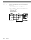
Analog Output Incorrect
Make certain of the type of Analog Output (voltage or current) that the channel is
equipped with; see “Identifying the Output Type” on page 94.
Use the
DIAGNOSTICS
->
DAC FULL SCALE
and
DIAGNOSTICS
->
DAC ZERO SCALE
menu items to
force the Analog Output to a known output. Then, adjust your readout device, panel
meter, PLC or data acquisition system to match.
Check the output selection jumpers; see “Output Selection” on page 94.
Auxiliary Function Pins Not
Operating
Make sure that the
AUX1 FUNCTION
or
AUX2 FUNCTION
SETUP menu items are set correctly;
if they are set to
DISABLED
then they will not operate.
The Auxiliary Function (“AUX1” and “AUX2”) pins must be connected to pin 10, not pin
8, to activate them.
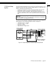
Sensitivity to EMI/RFI
To obtain maximum immunity to electromagnetic or radio frequency interference,
make certain that the shields of the transducer cables are connected to the “cable
shield connection screw” on the rear panel of the instrument. See “Connection of
Four- or Five-wire AC/AC-LVDT” on page 80, “External Arrangement of AC powered
SC1000 and SC2000” on page 27 and “External Arrangement of Model SC3004” on
page 33.
Non-linearity at the end of
the LVDT’s mechanical range
Most LVDTs have a usable measuring range that is smaller than their mechanical
range. See “Electrical Null and Transducer Mounting” on page 93 for information on
establishing the LVDT’s electrical null point to insure that the LVDT will be operated in
its usable measuring range.