


page 98 008-0608-00
12.2 Wiring
12.2.1 Channel
Connector
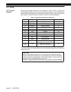
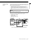
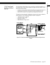
Connect the amplified transducer, in-line amplifier or DC-DC LVDT to a High-Level
Input channel by wiring it to the 12-pin connector of that channel. The Customer Infor-
mation Sheet that shipped with the instrument describes which cards are installed in
each channel. The pin-out for this connector is shown on the following table.
The Analog Output and Analog Return pins are electrically isolated from all other pins
on the instrument.
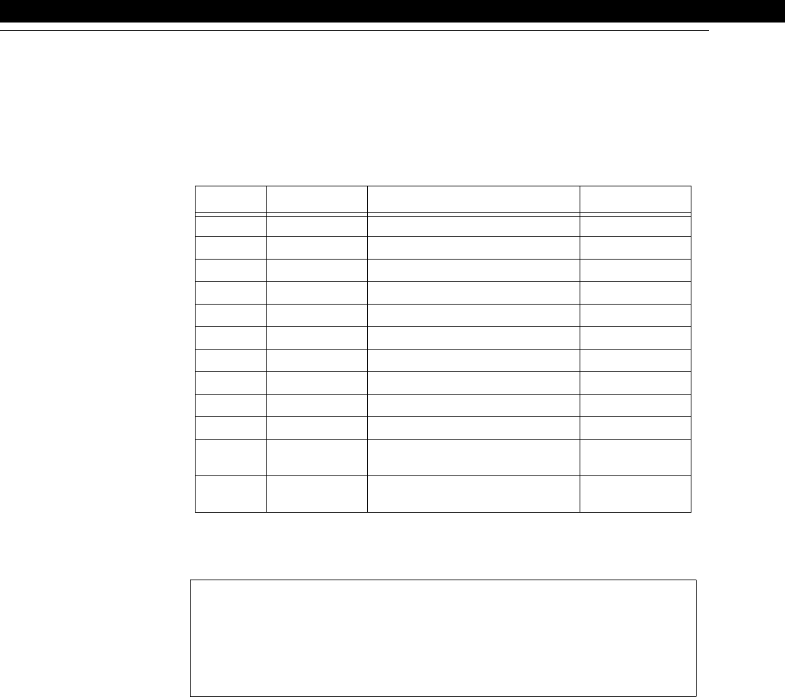
Table 1-6: High-Level Input Channel Pin Connections
Pin Label Function Reference Pin
1 (top) +EXC (+)Excitation 10
2 SHUNT1 Shunt Cal Relay 3
3 -SHUNT2 Shunt Cal Relay 2
4 -EXC (-)Excitation 10
5 +SIG (+)Signal 10
6 -SIG (-)Signal 10
7 +OUT Analog Output 8
8 -OUT Analog Return -
9 N/C No Connection -
10 DGND Digital Ground -
11 AUX1 Auxiliary Function 1
(connect to pin 10 to activate)
10
12
(bottom)
AUX2 Auxiliary Function 2
(connect to pin 10 to activate)
10
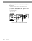
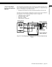
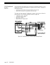
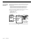
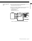
CAUTION
Identify the amplified transducer or in-line amplifier according to the Option
Code or model name as shown on its serial number tag. Use this information
to select the correct wiring diagram on the following pages. Incorrect wiring can
damage both the transducer and the instrument.
Failure to comply with these instructions may result in product damage.