


SC Series Instruction Manual page 99
High-Level Input Channel12
12.2.2 Bi-polar Voltage
Amplifiers
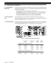
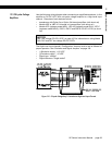
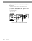
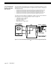
Use the following wiring diagram when connecting an amplified transducer, in-line
amplifier or DC-DC LVDT with a bi-polar voltage amplifier to a High-Level Input
channel. Examples of such devices include
• transducers with Option 2a or Option 2b internal amplifiers (with shunt cal)
• Models UBP or UBP-10 Universal In-Line amplifiers (with shunt cal)
• Models JEC (replaces model MDL), JEC-AG (replaces model DLA), JEC-C
(replaces model MDLC), DW7U, DW7C and DW7S DC-DC LVDTs (no shunt
cal)
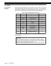
The High-Level Input channel’s Configuration Jumpers must be set as follows for
proper operation. See “Excitation and Signal Jumpers” on page 106.
• (+)Excitation supply: “+15 VDC”
• (-)Excitation supply: “-15 VDC”
• Signal type: “voltage”
• Signal reference: “single ended”
.
Figure 12-1: “Bi-polar Voltage Amp” Connection to High-Level Input Channel
NOTICE
See “Low Voltage DC-DC LVDTs” on page 105 for information on wiring Model
DLB, DLE and DLF low-voltage DC-DC LVDTs.