


page 34 008-0608-00
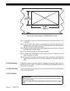
4.5.5 Case Removal
Step 1: Remove the four, silver rack-mounting ears from the left and right sides.
Step 2: Remove one Phillips screw from the top of the case.
Step 3: Remove two Phillips screws from the bottom of the black case cover.
Step 4: Remove the black case cover from the instrument.
Step 5: Remove eight Phillips screws from the rear panel, including the two cable
shield connection screws. NOTE: Do not remove the four screws which
secure the cooling fan to the rear panel.
Step 6: Remove the rear panel.
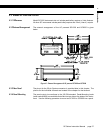
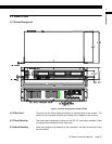
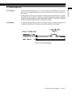
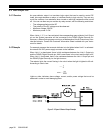
4.5.6 Rear Panel
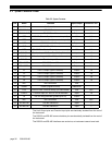
The pinout for the 25-pin System connector is provided later in this chapter.
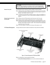
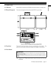
4.5.7 Internal Arrangement
User installable printed circuit boards will slide out of the rear of the case once the
case and rear panel have been removed as described above.
4.5.8 Cleaning
Turn off the instrument and unplug all connectors. Use a soft cloth or tissue and a
mild cleaner. Do not use liquid or aerosol cleaners. Do not allow any cleaner
inside the instrument.
4.5.9 Fuse Replacement
The power-line fuses are located within the instrument's power entry module on
the rear panel. Use two 2A, 250V fast-blow fuses (p/n 029-3026-00).
WARNING
Disconnect the power cord and all cables from the instrument before attempt-
ing to remove the case.
Failure to comply with these instructions could result in death or serious
injury.
CAUTION
Use a #0 Phillips screwdriver on the black screws to avoid damaging them.
Failure to comply with these instructions may result in product damage.