


SC Series Instruction Manual page 59
Strain-Gage Input Channel10
Chapter 10
Strain-Gage Input Channel
10.1 Features
The Strain-Gage Input channel provides a DC excitation voltage to and accepts
millivolt signals from strain-gage transducers. These millivolt signals are digitized,
converted into engineering units, and placed into the track, peak and valley data
values of the channel. Setup and calibration of the channel can be made manu-
ally through the SETUP mode or automatically if the transducers are equipped
with Signature Calibration. See “What is Signature Calibration?” on page 14.
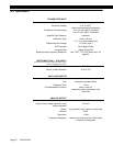
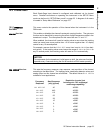
The analog-to-digital converter input circuit is ratiometric to the excitation voltage,
features adjustable digital, low-pass filtering, 12- to 18-bit resolution (depending
on the filter setting) and has several different mV/V input ranges. These many
input ranges allow ±50,000 count resolution (at the slowest filter setting) across a
wide variety of mV/V input ranges.
Three methods of calibrating the Strain-Gage Input channel to the transducer are
available: known-load calibration, shunt calibration and mV/V calibration. The
benefits of each are discussed in “
CALIBRATION TYPE
Menu Item” on page 67.
Two rear panel control inputs can be field-configured for such functions as remote
tare, disabling peak/valley detection and clearing the peak/valley values. A volt-
age or current digital-to-analog output is also provided.
Many diagnostic functions are performed automatically to insure correct wiring
and operation of the transducer.
FP2000 Transducers
The Strain-Gage Input channel has its own internal shunt resistor for use in Shunt
Calibration. It is not compatible with FP2000 mV/V output transducers that are
equipped with “Buffered Shunt Calibration”. If you wish to use Shunt Calibration
with an FP2000 transducer, use an FP2000 with Buffered Shunt cal and amplified
output (e.g. 5 VDC, 10 VDC or 4-20mA) connected to an SC's High-Level Input
channel.