


SC Series Instruction Manual page 29
Chassis Models4
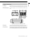
Removal of rear panel
The rear panel must be removed in order to install or remove channels.
Step 1: Remove the four black Phillips-head machine screws that secure the back
panel of the instrument to the case. These screws are located on the rear of
the case, one at each of the four corners.
Step 2: Remove the cable shield connection screw to allow the installation or
remove of channels per “Input or Output Channel Installation Procedure” on
page 42.
Remove of case from entire circuit
board assembly
Step 1: Remove the two Phillips-head screws that secure the front panel.
Step 2: Remove the front panel and disconnect its two connecting cables.
Step 3: Remove the four black Phillips-head machine screws that secure the back
panel of the instrument to the case. These screws are located on the rear of
the case, one at each of the four corners. Do not remove the cable shield
connection screw in the center.
Step 4: The circuit boards will slide out of the rear of the case as a unit.
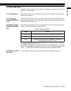
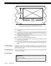
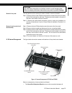
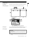
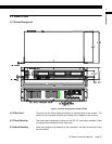
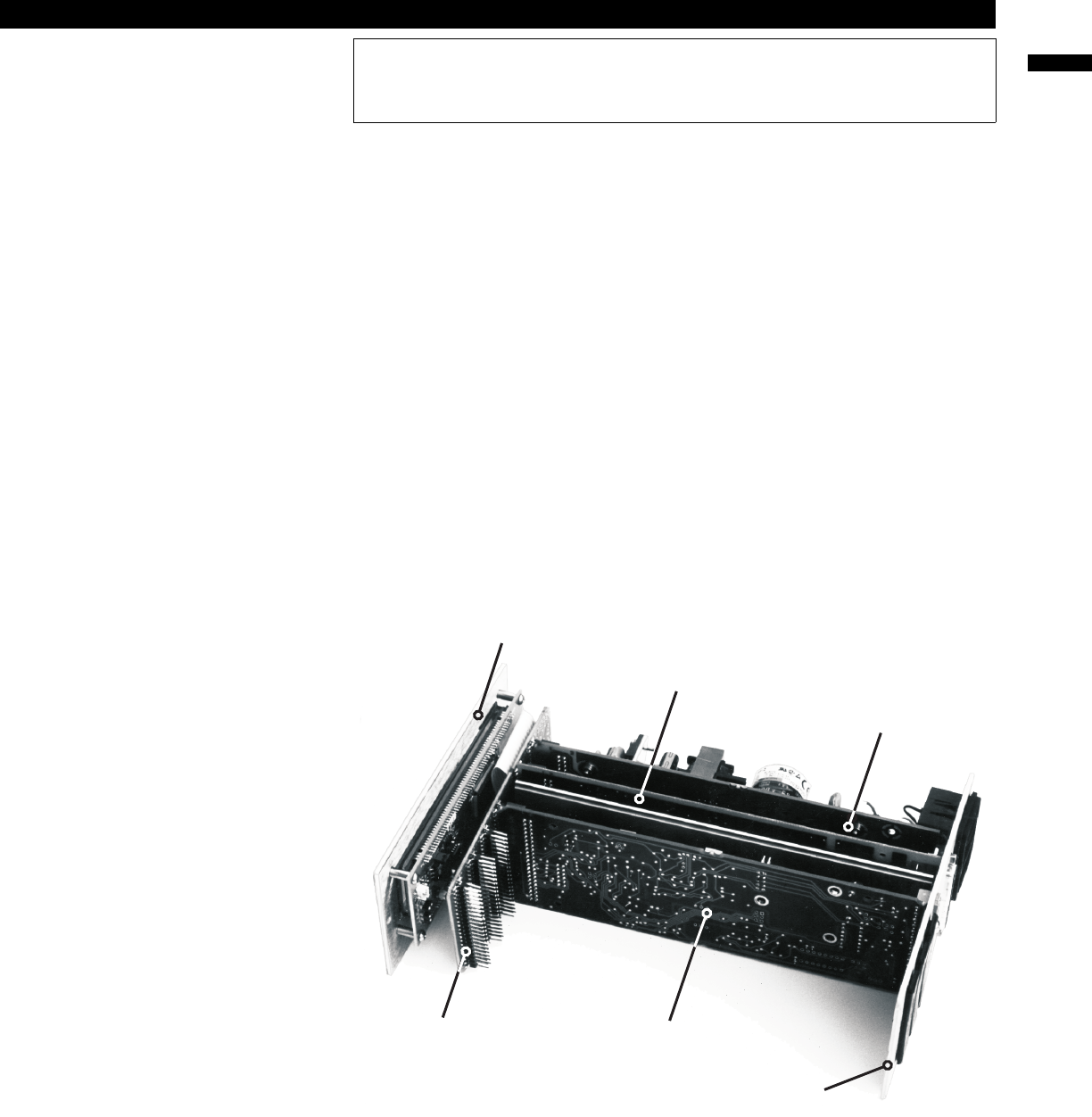
4.3.8 Internal Arrangement
The figure below shows the names and locations of the printed circuit boards.
Figure 4-3: Internal Arrangement of SC1000 and SC2000
Below is a description of each printed circuit board.
•The SensoBus Backplane Board serves as the connection between all
CAUTION
Use a #0 Phillips screwdriver on the black screws to avoid damaging them.
Failure to comply with these instructions may result in product damage.
Front Panel/Display Board
Assembly
Power Supply
Board
SensoBus Backplane
Board
Up to 4 Input or Output
Channel boards
(1 shown)
Microprocessor
Board
Rear Panel