


SC Series Instruction Manual page 77
Strain-Gage Input Channel10
10.7 Troubleshooting
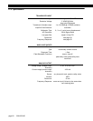
10.7.1 Error Messages
See “Error Messages” on page 151 for information relating to error messages.
10.7.2 Common Problems
and Solutions
Erratic Display
Check electrical connections for continuity and the transducer’s wiring code from
its Certificate of Calibration.
Make sure that the load on the transducer is constant.
Check millivolt input to the (+)Signal (“+SIG”) and (-)Signal (“-SIG”) pins with a
voltmeter.
+OVLD or -OVLD on Display
Indicates that the voltage across the (+)Signal (“+SIG”) and (-)Signal (“-SIG”) pins
is overranging or underranging the amplifier circuit. Make certain all wires are
connected properly.
If you remove all load from the transducer and you still see this message, the
(+)Excitation (“+EXC”) or (-)Excitation (“-EXC”) pins may be shorted to the (+)Sig-
nal (“+SIG”) or (-)Signal (“-SIG”) pins.
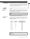
If you remove all load from the transducer and you get a numeric reading, the
transducer may have a high zero offset. Use the channel’s SETUP menu and set
DIAGNOSTICS
->
DISPLAY ADC
to “ON”; in the RUN mode this will allow the [VALUE] but-
ton to display raw A/D readings as a percentage of its full-scale. If the raw A/D
readings display more than +/-10% when there is no load on the transducer, the
transducer has a high zero offset.
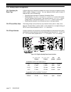
Analog Output Incorrect
Make certain of the type of Analog Output (voltage or current) that the channel is
equipped with; see “Identifying the Output Type” on page 76.
Use the
DIAGNOSTICS
->
DAC FULL SCALE
and
DIAGNOSTICS
->
DAC ZERO SCALE
menu items to
force the Analog Output to a known output. Then, adjust your readout device,
panel meter, PLC or data acquisition system to match.
Check the output selection jumpers; see “Output Selection” on page 76.
“
APPLY 00000
” on Power-up
The channel has detected that the transducer connected to the instrument is dif-
ferent than the one the channel was last calibrated with. Because the
CALIBRATION
TYPE
is set to either Shunt Calibration or mV/V Calibration, the instrument is
prompting you to apply zero load in order to auto-calibrate to this new transducer.
Do one of the following, depending on the situation:
• Re-connect the original transducer to the channel and re-start the instrument.
• Press [ENTER] to re-calibrate the channel to this new transducer using Shunt
or mV/V Calibration and accept the presently applied load as “0”. (In situa-
tions where one can’t apply “0” load to an absolute pressure transducer or a
load cell with a pre-load, you can change the
CALIBRATION DATA
->
ZERO-SCALE
VALUE
menu item from “0” to a load that can be applied. For example, 14.7
PSIA or the known pre-load on the load cell.
•Use the
CALIBRATE
menu item to perform a Known-Load Calibration with this
new transducer.
Auxiliary Function Pins Not
Operating
Make sure that the
AUX1 FUNCTION
or
AUX2 FUNCTION
SETUP menu items are set cor-
rectly; if they are set to
DISABLED
then they will not operate.
The Auxiliary Function (“AUX1” and “AUX2”) pins must be connected to pin 10,