


SC Series Instruction Manual page 85
AC/AC-LVDT Input Channel11
11.5.2
DISPLAY SETUP
Sub-Menu
This menu controls how data values are displayed by the channel and transmitted
via serial communications.
DISPLAY. DIGITS
Menu Item
Selects the number of digits displayed by the channel. The choices are:
•“
5 DIGIT-BIPOLAR
” displays both positive and negative numbers with five full dig-
its (±99999).
•“
6 DIGIT-UNIPLOAR
” displays positive numbers with six full digits (999999) and
negative numbers with five full digits (-99999).
•“
7 DIGIT UNIPOLAR”
displays positive number with seven full digits (9999999)
and negative numbers with six digits (-999999).
DISPLAY. DECPT
Menu Item
Selects the decimal point location on the channel’s display and serial communica-
tions output. Use the [UP] and [DOWN] buttons to move the decimal point to the
right and left.
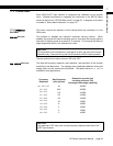
DISPLAY. COUNT-BY
Menu Item
Determines by what value the display increments or decrements. This will make
the display less sensitive to a noisy signal. The choices are:
•“
00001
”
•“
00002
”
•“
00005
”
•“
00010
”
•“
00020
”
•“
00050
”
•“
00100
”
•“
00200
”
DISPLAY. UNITS
Menu Item
Specifies the four character label that is displayed to the right of the channel’s val-
ues.
When a character position is flashing press the [UP] or [DOWN] button to change
the character. Press [ENTER] to advance to the next character.
DISPLAY. AVERAGE
Menu Item
Controls the speed with which the channel’s display values will update. Display
averaging does not affect the channel’s analog output or its peak/valley detection,
which will proceed at the speed selected by the ”
OPERATION
->
FREQ. RESPONSE
” menu
item. The choices are:
•“
ON
” means that the display will update four times each second. The channel’s
values will be averaged for 1/4 second, then displayed.
•“
OFF
” means that the channel’s display will update as quickly as possible.
11.5.3
AUXn FUNCTION
Menu
Items
The
AUX1 FUNCTION
and
AUX2 FUNCTION
menu items determine what happens when the
Auxiliary Function pins (labeled as “AUX1” and “AUX2”) on the channel’s connec-
tor are activated. These pins are “activated” when they are connected to the
DGND pin. The choices are:
•“
DISABLED
” means that activating the pin does nothing.
•“
TRACK HOLD
” means that the tracking, peak and valley values will not be
NOTICE
This menu item doesn’t change the mathematical scaling of the channel’s val-
ues; that can be changed by altering the “
CALIBRATION DATA
->
KNOWN POINT X/Y
”
menu items and then performing a re-calibration.