


page 80 008-0608-00
11.2 Wiring
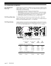
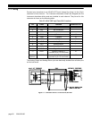
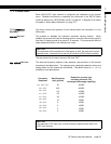
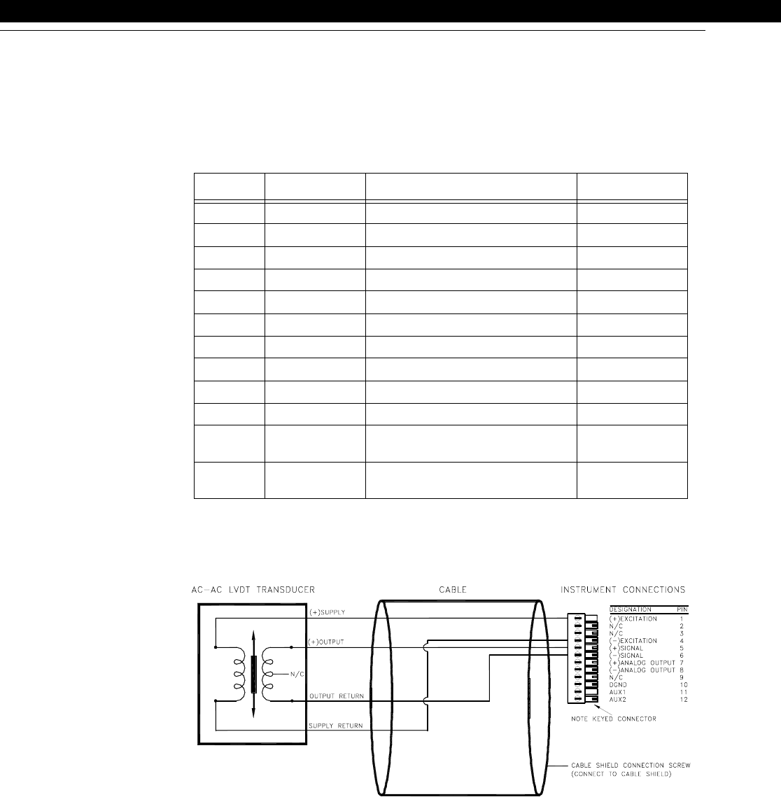
Connect your transducer to an AC/AC-LVDT Input channel by wiring it to the 12-pin
connector of that channel. The Customer Information Sheet that shipped with the
instrument describes which cards are installed in each channel. The pin-out for this
connector is shown on the following table.
The Analog Output and Analog Return pins are electrically isolated from all other pins
on the instrument.
Figure 11-1: Connection of Four- or Five-wire AC/AC-LVDT
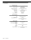
Table 5-5: AC/AC-LVDT Input Channel Pin Connections
Pin Label Function Reference Pin
1 (top) +EXC (+)Excitation 10
2 N/C No connection
3 N/C No connection
4 -EXC (-)Excitation 10
5 +SIG (+)Signal 10
6 -SIG (-)Signal 10
7 +OUT Analog Output 8
8 -OUT Analog Return -
9 N/C No connection
10 DGND Digital Ground -
11 AUX1 Auxiliary Function 1
(connect to pin 10 to activate)
10
12
(bottom)
AUX2 Auxiliary Function 2
(connect to pin 10 to activate)
10