


page 36 008-0608-00
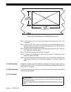
5.2 System Connector Pinout
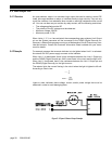
The Limit Output pins and Function Input pins are electrically isolated from the rest of
the instrument.
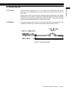
The RS-232 and RS-485 communications pins are electrically isolated from the rest of
the instrument.
The RS-232 and RS-485 interfaces are exclusive; an instrument cannot have both.
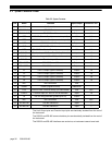
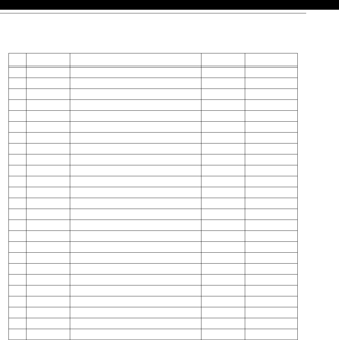
Table 5-2: System Connector
Pin Name Function Input/Output Reference Pin
1 N/C No Connection N/A
2 RS-232 IN RS-232 Data In Input 7
3 RS-232 OUT RS-232 Data Out Output 7
4 CTS RS-232 Clear to Send (connected to pin 5) N/A N/A
5 RTS RS-232 Request to Send (connected to pin 4) N/A N/A
6 DSR RS-232 Data Set Ready Output 7
7 GND RS-232/RS-485 reference Reference -
8 DCD RS-232 Data Carrier Detect (not connected) N/A N/A
9 FUNC 2 Function Input #2:.Clear Peak/Valley & Limits Input 19
10 FUNC 1 Function Input #1: Tare Off for all channels Input 19
11 FUNC 0 Function Input #0 Input 19
12 RS-485 TB RS-485 Transmit B Output 7
13 RS-485 TA RS-485 Transmit A Output 7
14 L1 Limit 1 Output (Open Collector) Output 19
15 L2 Limit 2 Output (Open Collector) Output 19
16 L3 Limit 3 Output (Open Collector) Output 19
17 L4 Limit 4 Output (Open Collector) Output 19
18 N/C No Connection N/A
19 DGND DGND (Digital Ground) Reference
20 DTR RS-232 Data Terminal Ready (not connected) N/A N/C
21 FUNC 3 Function Input #3: Tare On for all channels Input 19
22 RI RS-232 Ring Indicator (pulled up to 5V) Output
23 N/C No Connection N/A N/C
24 RS-485 RB RS-485 Receive B Input 7
25 RS-485 RA RS-485 Receive A input 7