


SC Series Instruction Manual page 55
Limits9
9.3 Limit Menus
9.3.1 Overview
There are four, eight, twelve or sixteen Limit menus depending on how many
Relay Output channels are installed in the instrument. These menus determine
the operation of the each of the limits.
If no Relay Output channels are installed, there are four Limit menus which control
the operation of the open-collector Limit Outputs on the System connector.
Detailed instructions on operating the instrument in the SETUP Menu mode can
be found in “SETUP Menu mode” on page 23. A diagram of all menus is located
in “Setup Menu Reference” on page 157.
9.3.2
LIMIT.ENABLE
Menu
Item
This enables or disables the operation of this limit. The two options for this menu
item are “
ON
” and “
OFF
”.
9.3.3
LIMIT.SETPOINT
Menu Item
This is the numeric value in engineering units for the signal level that activates the
limit.
9.3.4
LIMIT.RETURN PNT
Menu Item
This is the numeric value at which the limit deactivates. In general, this number
should differ from the set point values by at least 1% of full scale.
Carefully consider what value should be entered for the RETURN POINT. If the
signal is expected to approach the SET POINT from a lower value, the RETURN
POINT value should be less (algebraically) than the SET POINT. If the signal is
expected to approach the SET POINT from a higher level, the RETURN POINT
should be higher (algebraically) than the SET POINT.
9.3.5
LIMIT.ENERGIZE
Menu Item
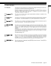
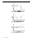
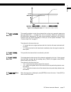
This specifies when to activate the limit relative to the set point and return point.
The options for this menu item are:
•“
SIGNAL > SETPOINT
” means the limit will activate when the signal is higher than
the set point.
•“
SIGNAL < SETPOINT
” means the limit will activate when the signal is lower than
the set point.
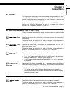
•“
SIGNAL INSIDE
” means the limit will activate when the signal is in between the
set point and the return point.
•“
SIGNAL OUTSIDE
” means the limit will activate when the signal is not in between
the set point and the return point.
The figures below further illustrate the differences between these settings.