


page 94 008-0608-00
11.7 Analog Output Configuration
11.7.1 Identifying the
Output Type
An AC/AC-LVDT Input channel is available with one of two types of digital-to-analog
(DAC) outputs: voltage or current. You can determine which type of output a channel
has by one of three ways:
• Consulting the instrument’s Customer Information Sheet
• Examining the
SYSTEM MENU
->
CONFIGURATION
->
CHANNEL
nn
TYPE
menu item where nn is
the number of the channel. If the channel’s type is
AC-AC LVDT V
, it has a voltage
output. If the channel’s type is
AC-AC LVDT I
, it has a current output.
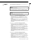
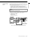
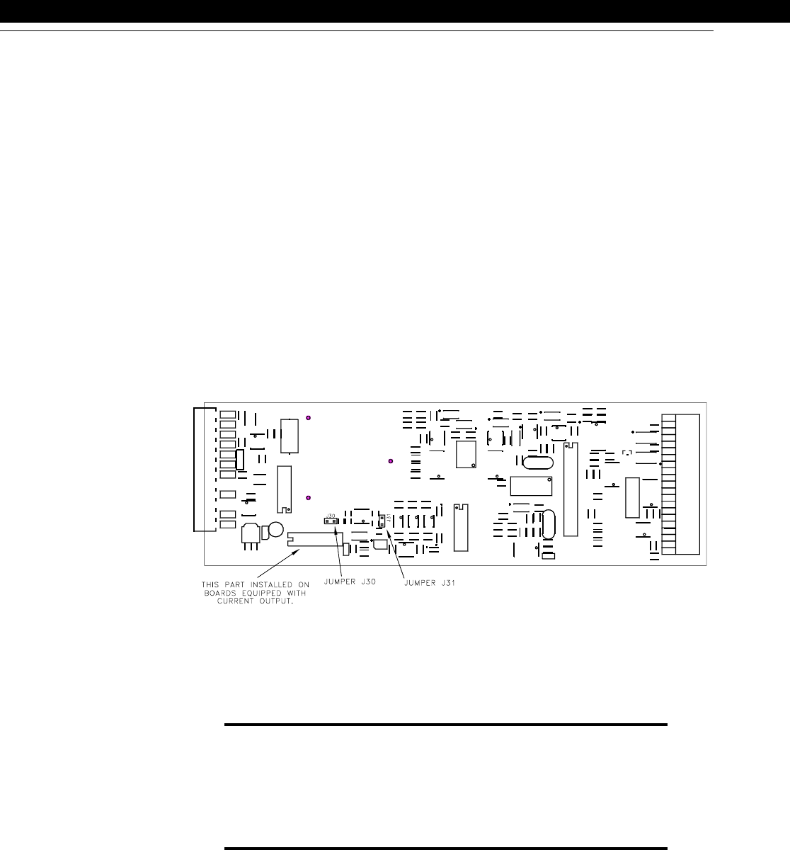
• Examining the channel’s circuit board as shown in the figure below.
11.7.2 Channel Menu
Items
The Analog Output can be driven by any channel’s track, peak or valley value.
See the “Channel Menu” section earlier in this chapter for a complete listing of SETUP
menu items available on the
DAC. SETUP
sub-menu.
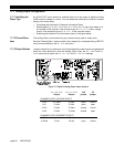
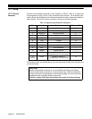
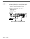
11.7.3 Output Selection
Jumpers located on the channel’s circuit board determine what outputs are generated
when the value selected to drive the Analog Output (from the
DAC. CHANNEL
and
DAC.
SOURCE
menu items) equals the
DAC. FULL SCALE
and
DAC. ZERO SCALE
settings.
Figure 11-2: Digital-to-Analog Output Jumper Locations
DAC. ZERO SCALE
Output
DAC. FULL SCALE
Output
J30
jumper
J31
jumper
CHANNELS WITH VOLTAGE OUPUT
0-5V 2.5 Volts 5 Volts open closed
±5V 0 Volts 5 Volts open open
0-10V 5 Volts 10 Volts closed closed
±10V 0 Volts 10 Volts closed open
CHANNELS WITH CURRENT OUTPUT
4-20mA 4 mA 20 mA open open
4-20mA 12 mA 20 mA open closed