


LF-72/74
F-16 F-16
Return to Section TOC Return to Section TOC Return to Section TOC Return to Section TOC
Return to Master TOC Return to Master TOC Return to Master TOC Return to Master TOC
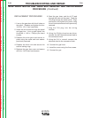
REMOVAL PROCEDURE
1. Remove the input power ( 42VAC )
from the LN72/LN74 unit.
2. Using the 5/16 nut driver remove the 5
screws holding the cover.
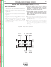
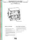
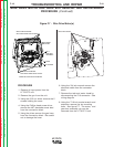
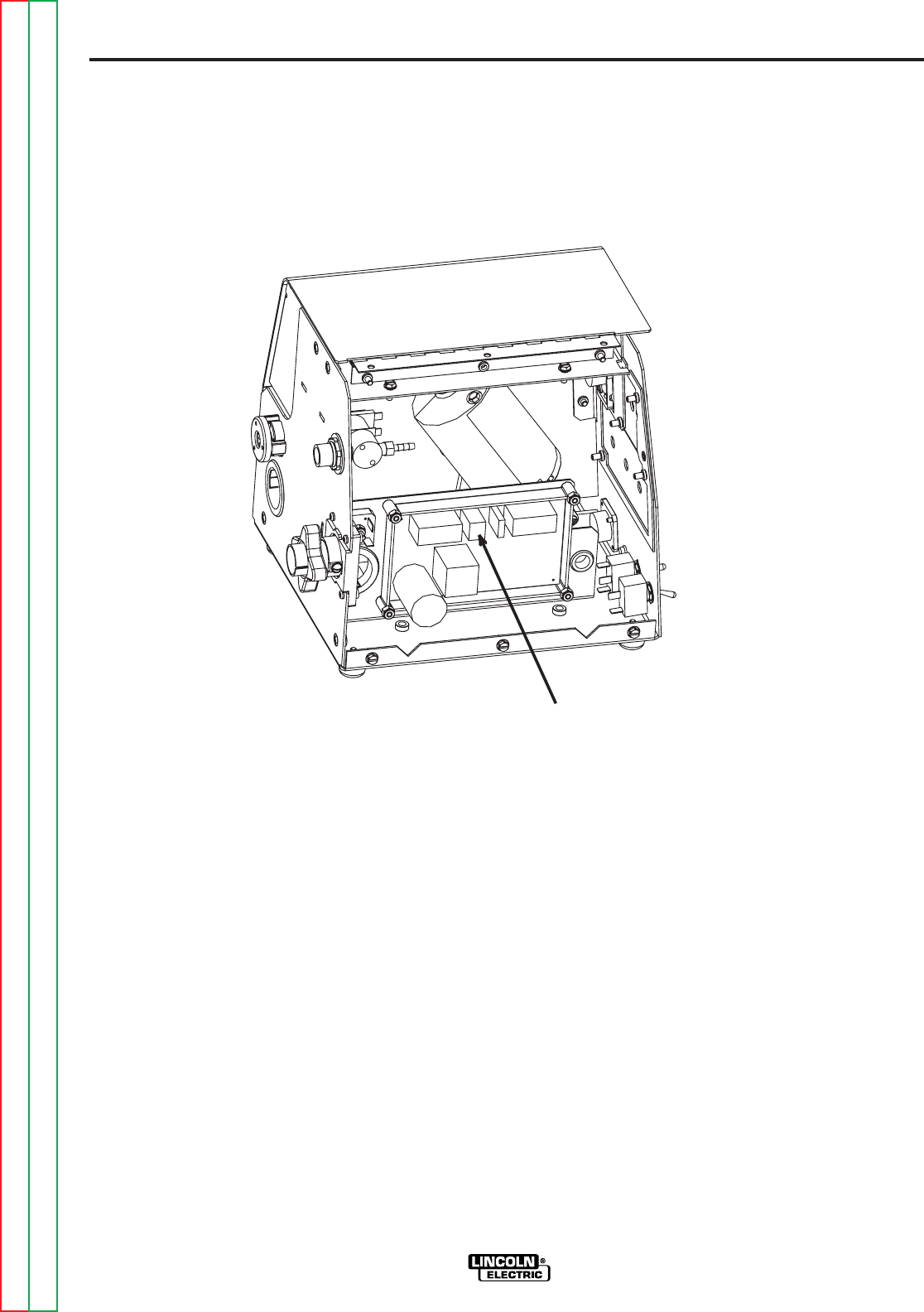
3. Locate the control board (see figure F.6)
and remove the harness plugs on the
control board. Observe static electricity
precautions.
4. Remove the 4 nuts holding the board
using the 3/8 inch nut driver, and remove
the board.
REPLACEMENT PROCEDURE
1. Remove the new control board from the
static bag and place it on the 4 studs.
2. Reassemble the 4 nuts and tighten hand
tight.
3. Reassemble the harness plugs.
4. Reassemble the case.
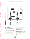
TROUBLESHOOTING AND REPAIR
CONTROL PC BOARD REMOVAL AND REPLACEMENT PROCEDURE
(Continued)
Figure F.6 - PC Board Location
CONTROL BOARD