


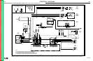
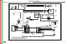
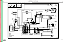
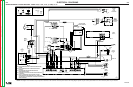
ELECTRICAL DIAGRAMS
G-9
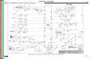
LF-72/74
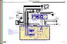
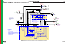
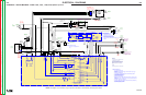
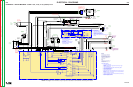
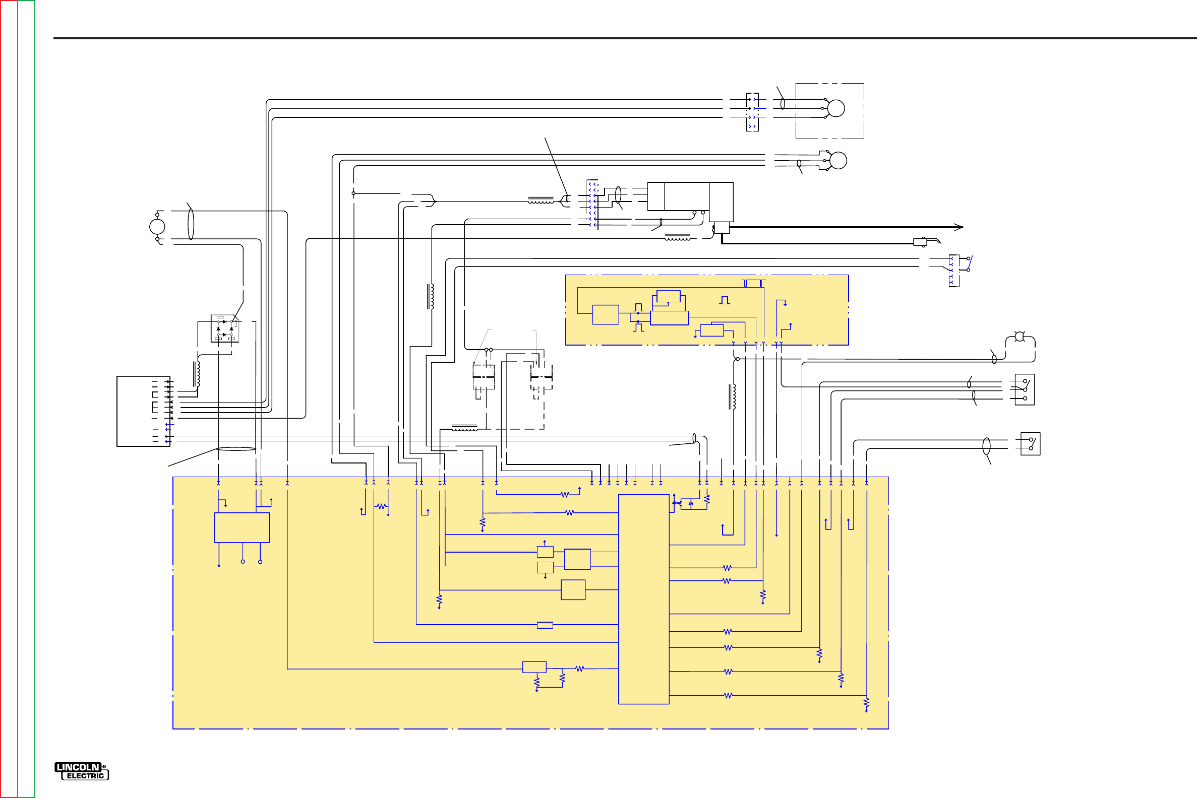
SCHEMATIC - ENTIRE MACHINE - CODE 11195, 11196, 11197, (G4942) LF-74
A
D
C
B
E
554
556
T
RIGGER
C
ONNECTOR
J13
559
515
558
COLD FEED
S1
FEED
PLATE
T
RIGGER
I
NPUT
67
556
J1-4
J1-5
J1-11
J1-12
J1-15
559
1
4
3
2
6
5
P
10
8
7
M
OTOR /
GEARBOX
W
B
L5
515
558
589
587
554
A
550
551
550
576
577
575C
553
552
2
4
KEY
580
552A
605
606
601
607
608
515A
THERMAL LED
1W
563
562
575B
562
1B
1W
1B
10K/2W
2
1
P7
4
3
REMOTE
C
ONTROL
VOLTAGE
POTENTIOMETER
(OPTIONAL)
7
5A
7
6A
77A
W
IRE FEED
S
PEED
C
ONTROL
P
OTENTIOMETER
1
0K/2W
589
TRIGGER
INTERLOCK
S2
587
-
+
580
4
2
5
52A
41
552B
TIMER KIT
(OPTIONAL)
S
CHEMATIC=
M20336
J60-6
6
01
5
15A
605
6
07
6
08
606A
552
5
53
GAS
SOLENOID
O
UTPUT
C
ONTROL
J12
2
C
4
D
7
7A
E
7
6A
F
7
5AG
4
1
I
J
42
K
L
M
6
7
N
REMOTE
V
OLTAGE
C
ONTROL
SENSE
552B
2-STEP
GAS PURGE
L1
577
5
76
5
75
7
5
7
6
77
L
2
L3
575
575C
575B
2
4-42VAC
L4
562
5
63
1
5 VDC in
2
STEP
position
5 VDC
when lit
3
8VDC at
42VAC input
with control
board
disconnected.
60VDC with
control board
connected
1
.6V @ 100 IPM
30.6V @ 800 IPM
Motor is located
behind
glastic panel
Lights when motor
current exceeds
3.75 Amps for an
extended time.
O
ff = 0 VDC
O
CV = 59 VDC
On = 7.7 VDC
Locatedon
CaseFront
Locatedon
CaseFront
Locatedon
CaseFront
Locatedon
case back
Values for CV300. Others
m
ay be different.
0 VDC @ 0 = 5.8 Arc Volts
6.6 VDC @ 10 = 40 ArcVolts
0 VDC MIN. WFS
5 VDC MIN. WFS
Trigger Interlock does not
stop welding when the
arc is broken. Pull and
release trigger to end the
weld.
15 VDC Open
0 VDC Closed
15 VDC Open
0 VDC Closed
Gearbox ratio is 2:47
Motor is atelectrode
potential
Start-Up
On power-up, the LF-74 will light the
motor thermal LED for 0.5 seconds.
If the feeder is powered-up with the
trigger depressed, welding will not start
until the trigger is released and then
depressed again.
Notes
The WFS range of this code of LF-74 is
100-800 ipm. The WFS range of the
LF-72 is 50-800 ipm.
T
o Power Source Electrode Connection
750 ohm
+15V
750 ohm
TRIGGER
OPEN = 0V
CLOSED = 8V
MOTOR
CURRENT
SENSE
SCALING
MOTOR
VOLTAGE
SENSE
BRAKE
FET
DRIVE
FET
0.1 ohm
MOTOR
DRIVE
CIRCUIT
+ POWER
J
1-1
+5V
FILTER
TACH
FEEDBACK
0-5V PULSE SIGNAL
FREQUENCY = SPEED
J1-9
J
1-13J1-3
100K
ohm
WIRE
FEED
SPEED
0V = MIN SPEED
5V = MAX SPEED
+5V
J
1-8
200 ohm
GAS
SOLENOID
SOLENOID
FET
10K
ohm
0.25
ohm
J
1-2
J1-6 J1-16
+POWER
C
OM
COM
BOARD
POWER
SUPPLY
J14-1
J
14-9
MOV
20
ohm
MACHINE
OUTPUT
ENABLE
J
14-8
J14-14
J14-2
J
14-5
+5V
BURNBACK
0V = 0.02 SECONDS
5V = 0.25 SECONDS
J
14-4
EXTERNAL
GAS
SOLENOID
CONTROL
LOW = CONTROL AT CONTROL BOARD
HIGH = CONTROL AT TIMER BOARD
J
14-12
J
14-13
PROGRAM
DO NOT USE
NOT FIELD PROGRAMMABLE
J14-7
200 ohm
THERMAL
LED
5V = OFF
4V OR LESS = ON
J14-10
COLD
FEED
LOW = DISABLE
HIGH = ENABLE
J
14-16
J
14-11
J
14-15
J14-3
GAS
PURGE
LOW = DISABLE
HIGH = ENABLE
+15V +15V
TRIGGER
INTERLOCK
LOW = DISABLE
HIGH = ENABLE
+
15V
MICRO
CONTROLLER
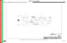
COMMON ANALOG P.C. BOARD
SCHEMATIC =G4559
Control Board Summar
y
• Has on-board power supply.
• Receives switch signals from Trigger, Cold Feed, Gas Purge, Trigger
Interlock
• Reads WFS potentiometer.
• Communicates with optional timer kit to control burnback, postflow.
• Controls motor speed with PWM.
• Turns Gas Solenoid on, off.
• Reads the motor tachometer.
• Monitors motor current, lights yellow thermal LED if over 3.75 amps for an
extended time period. LED remains lit for 30 – 60 seconds to allow motor
to cool.
• Does NOT support Run-in atthis time.
• Operates on 24-42 VAC. Maximum WFS and/ormaximum pull forcemay
be less when operating at 24 VAC.
• Does NOT operate on 115 VAC.
J60-5 J60-8
J60-7J60-1
J60-3
+15V
COM
COM
BURNBACK
P
OT
PREFLOW &
P
OSTFLOWTIMER
L
OGIC
POSTFLOW
POT.
A
b
PREFLOW
TIME FIXED
AT 30msec
c
D
POSTFLOW
TIME RANGE
.
25 - 10 SEC
FIXED
PULSE
WIDTH
GENERATOR
A
c
5V SIGNAL
GAS FLOW
E
NABLE
Locatedon Case Front
I
NPUT
OUTPUT
b
15V SIGNAL
100 msec PULSES
TOGGLE GAS FLOW ON/OFF
D
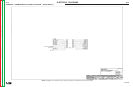
T
ime
r
B
oard Summar
y
•
Has potentiometers for burnback and postflow.
•
Preflow fixed at 30msec.
• Burnback range is 0 to 0.25sec.
• Postflow range is 0.25 to 10sec.
•
Receives “Gas FlowEnable” signal.
• Outputs 100 msec pulses to turn Gas Flow On, Gas
Flow Off.
J2-1 J2-2 J2-3 J2-4 J2-5 J2-6 J3-1 J3-2
NOT USED
NOT USED
Connector located
b
y sheetpanel
Motor resistance
is 1.5 ohms
Connector located
behindcase front
Leads Pass through
toroid 2 times.
Coil
measures
21 ohms
INDEX
MOLEX
+5V
+15V
R
U
B
4
3
2
1
4
3
2
1
4
32
1
A
B
521
5
22
P
4
P11
P6
551A
521
522
5
51B
NORMAL
SPEED
4
32
1
A
B
HIGH
TORQUE
L6
5
51
Locatedon
CaseFront
Locatedon
C
ase Front
Locatedon
CaseFront
Locatedon
CaseBack
L
ocatedon
Sheet Panel
Leads
Pass
through
toroid 2
t
imes.
LeadsPass through
t
oroid 3 times.
Leads Pass
through
toroid 2 times.
5
51A
LeadsPass
t
hrough
toroid 2
times.
C
onnectorlocated
o
n sheetpanel
P11
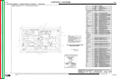
Motor Connecter Summar
y
• High Torque Setting engages
Machine Select by connecting Pins 1
and 2 on Connector J2.
• High Torque not available on Normal
S
peed Model.
•
Normal Speed Setting not available
on High Torque Model.
20 OHM = OUTPUT ENABLED
HIGH IMPEDANCE = OUTPUT DISABLED
L
eadsPass
through
toroid 2
times.
5
63
40 pole
ring
magnet
5 VDC
284 pulses/sec @ 100 IPM
1139 pulses/sec @ 400 IPM
G-9
NOTE: This diagram is for reference only
. It may not be accurate for all machines covered by this manual.
Return to Section TOC Return to Section TOC Return to Section TOC Return to Section TOC
Return to Master TOC Return to Master TOC Return to Master TOC Return to Master TOC