


LF-72/74
F-18 F-18
Return to Section TOC Return to Section TOC Return to Section TOC Return to Section TOC
Return to Master TOC Return to Master TOC Return to Master TOC Return to Master TOC
TROUBLESHOOTING AND REPAIR
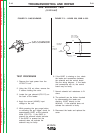
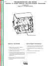
WIRE DRIVE MOTOR AND GEAR BOX REMOVAL AND REPLACEMENT
PROCEDURE
(Continued)
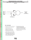
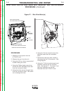
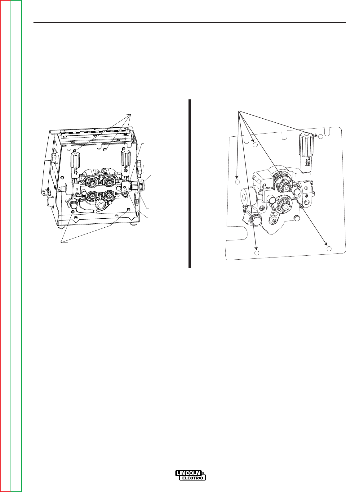
Figure F.7 - Wire Drive Motor(s)
PROCEDURE
1. Remove th input power from the
LF72/LF72 unit.
2. Remove the gun from the unit.
3. Using the 5/16 nut driver remove the 5
screws holding the cover.
4. Using the Phillips head screw driver
remove the #67 electrode sense lead
from the connection block.
5. Using the pliers remove the gas hose
from the connection block. Be careful
not to damage the hose.
6. Using the 3/4 inch wrench remove the
electrode cable from the connector
block.
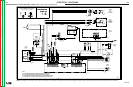
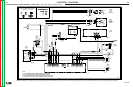
7. Remove the tach and motor leads by
disconnecting the P10 connector. See
wiring diagram.
8. Using the 7/16 inch socket wrench and
extension remove the six mounting
bolts. See figure F.7. The motor, and
gear box assembly can now be
removed from the LF72/LF74 unit.
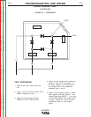
O-RING
MOUNTING SCREWS*
SECURING WIRE DRIVE PANEL
MOUNTING SCREWS *
SECURING WIRE DRIVE PANEL
INCOMING
BUSHING
BALL
BUSHING
ASSEMBLY
*REMOVE 6 MOUNTING SCREWS
SET SCREW
MOUNTING BOLTS