


LF-72/74
OPERATION
BB-5 BB-5
Return to Section TOC Return to Section TOC Return to Section TOC Return to Section TOC
Return to Master TOC Return to Master TOC Return to Master TOC Return to Master TOC
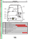
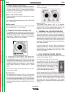
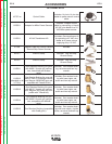
1. WIRE FEED SPEED KNOB
The large, calibrated wire feed speed knob makes for
easy and accurate adjustment of the wire feed speed.
The knob rotates 3/4 turn. Turn the knob clockwise to
increase the wire feed speed, and counter clockwise
to reduce the wire feed speed.
K2426-1 and K2426-2 models:
These wire feeders are factory configured for normal
speed operation.
The normal wire feed speed range is 100 to 800 in/min
(2.5 - 20.3 m/min).
K2426-3 model:
The wire feed speed range on the extra torque model
is 50 to 400 in/min (1.3 – 10.2 m/min)
2. REMOTE VOLTAGE CONTROL KIT
The optional remote voltage control kit adjusts the arc
voltage from the minimum to the maximum voltage of
the welding power source. Rotate the knob counter-
clockwise to reduce the arc voltage and rotate the
knob clockwise to raise the arc voltage.
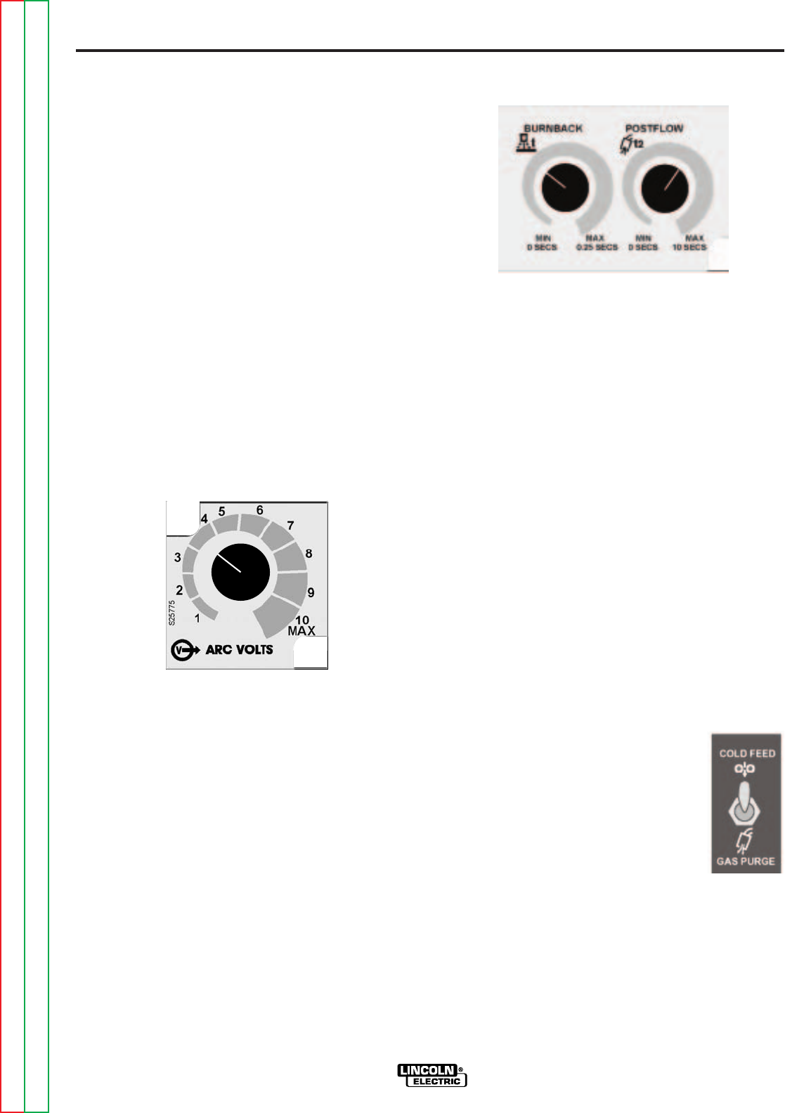
3. BURNBACK AND POSTFLOW TIMER KIT
The optional Burnback and Postflow Timer Kit gives
control over the shielding gas at the end of the weld
and prepares the end of the wire for the next arc start.
Additional shielding gas protection is often required
when welding aluminum, stainless steel or exotic
alloys.
When stitch welding, set the postflow time to maxi-
mum for best results.
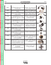
Burnback Timer
The burnback timer range is OFF to 0.25 seconds.
The burnback timer controls the additional amount of
time the power source output remains ON after the
wire drive has stopped feeding wire. Burnback adjust-
ment prevents the wire from sticking to the weld at the
end of a weld and helps to condition the wire for the
next weld.
To set the burnback time, adjust the knob to approxi-
mately 0.03 seconds and then decrease or increase
the time as desired.
Postflow Timer
The postflow timer range is OFF to 10 seconds.
Postflow is the time from when the power source out-
put turns OFF until the postflow timer expires. Use
postflow to protect the weld while the weld cools.
4. THERMAL LED, MOTOR OVERLOAD
The thermal light illuminates when the wire drive
motor draws too much current. If the thermal light illu-
minates, the wire drive will automatically shutdown for
up to 30 seconds to allow the motor to cool. To start
welding again, release the gun trigger, inspect the gun
cable, liner (and conduit). Clean and make repairs as
necessary. Start welding again when the problem has
been safely resolved.
For best results, keep the gun cable and conduit as
straight as possible. Perform regular maintenance
and cleaning on the gun liner, conduit and gun.
Always use quality electrode, such as L-50 or L-56
from Lincoln Electric.
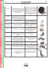
5. COLD FEED/GAS PURGE SWITCH
Cold Feed and Gas Purge are combined into a single
spring centered toggle switch.
To activate Cold Feeding, hold the switch
in the UP position. The wire drive will feed
electrode but neither the power source
nor the gas solenoid will be energized.
Adjust the speed of cold feeding by rotat-
ing the WFS knob. Cold feeding, or "cold
inching" the electrode is useful for thread-
ing the electrode through the gun.
Hold the toggle switch in the DOWN posi-
tion to activate Gas Purge and let the shielding gas
flow. The gas solenoid valve will energize but neither
the power source output nor the drive motor will be
turned on. The Gas Purge switch is useful for setting
the proper flow rate of shielding gas. Flow meters
should always be adjusted while the shielding gas is
flowing.