


LF-72/74
F-10 F-10
Return to Section TOC Return to Section TOC Return to Section TOC Return to Section TOC
Return to Master TOC Return to Master TOC Return to Master TOC Return to Master TOC
TROUBLESHOOTING AND REPAIR
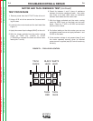
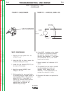
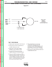
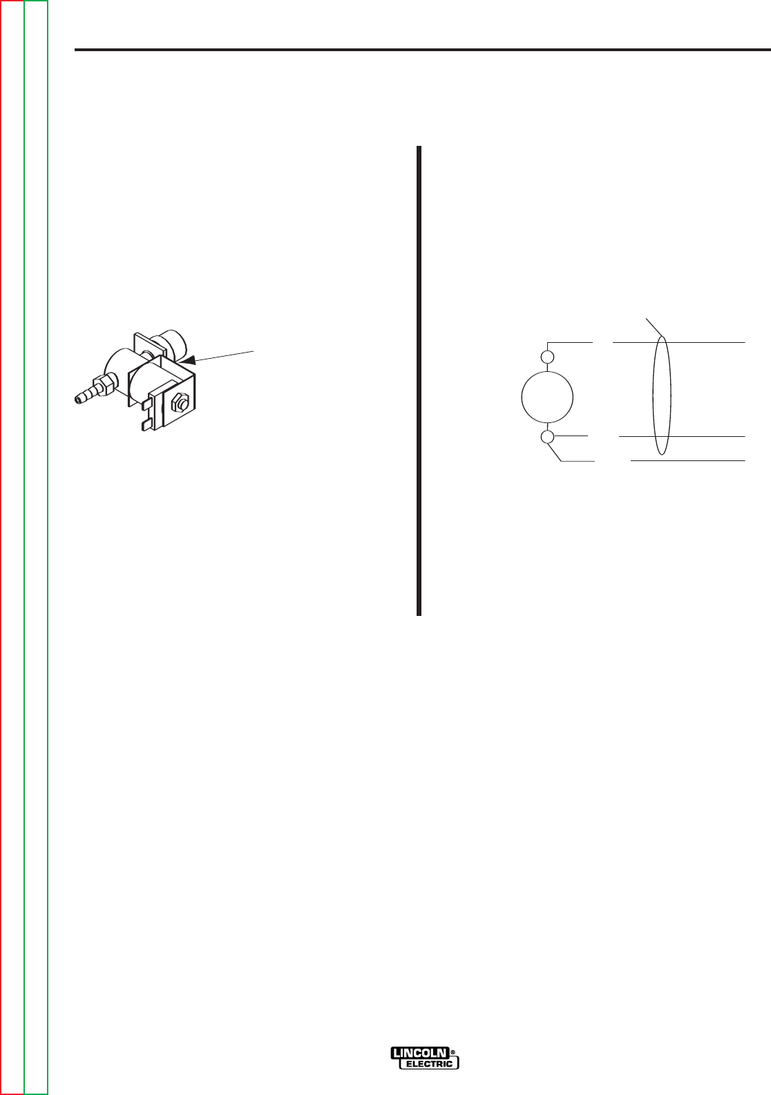
GAS SOLENOID
552B
552
553
Off = 0 VDC
OCV = 59 VDC
On = 7.7 VDC
Located on
case back
GAS
SOLENOID
Coil
measures
21 ohms
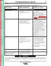
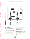
GAS SOLENOID TEST
(continued)
TEST PROCEDURE
1. Remove the input power from the
LF72/LF74 unit.
2. Using the 5/16 nut driver, remove the
5 screws holding the cover.
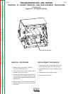
3. Locate the gas solenoid (FIG F.2) on
the back of the feeder.
4. Apply the correct (42VAC) input
voltage to the unit.
5. While pressing the gas purge button
or activating the gun trigger, check for
approximately 8VDC at the solenoid
leads (FIG F.3). If the 8VDC is
present the solenoid should activate.
If the 8VDC is present but the
solenoid does not activate the
solenoid may be faulty.
6. If the 8VDC is missing or low, check
the leads and connections between
the solenoid and the control board.
See the wiring diagram. If the leads
and connections are ok, the control
board may be faulty.
7. Normal solenoid coil resistance is 21
ohms.
8. The solenoid can be further checked
by disconnecting the leads and
applying 12VDC directly to the
terminals. If the solenoid does not
activate the solenoid is faulty.
9. Reconnect the leads and replace the
cover.
FIGURE F.3 – LEADS 552, 552B & 553
FIGURE F.2 - GAS SOLENOID