


LF-72/74
INSTALLATION
AA-12 AA-12
Return to Section TOC Return to Section TOC Return to Section TOC Return to Section TOC
Return to Master TOC Return to Master TOC Return to Master TOC Return to Master TOC
ASSEMBLY OF DRIVE ROLLS AND WIRE
GUIDES
ELECTRIC SHOCK can kill.
• Turn the input power OFF at the
welding power source before instal-
lation or changing drive rolls and/or
guides.
• Do not touch electrically live parts.
• When inching with the gun trigger, electrode and
drive mechanism are "hot" to work and ground
and could remain energized several seconds
after the gun trigger is released.
• Only qualified personnel should perform mainte-
nance work.
------------------------------------------------------------------------
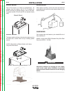
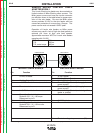
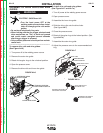
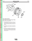
To remove drive rolls and wire guides:
(See Figure AA.6)
1. Turn power off at the welding power source.
2. Remove the outer wire guide.
3. Rotate 4 triangular rings to the unlocked position.
4. Open the pressure arms.
5. Remove the drive rolls and inner wire guide.
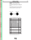
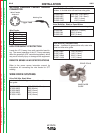
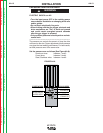
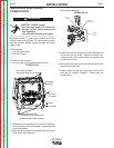
To install drive rolls and wire guides:
(See Figure AA.7 and AA.7a)
1. Turn off power at the welding power source.
2. Open pressure arms.
3. Assemble the inner wire guide.
4. Slide the drive rolls onto the drive hubs.
(See figure
AA.7)
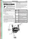
5. Close the pressure arms.
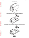
6. Rotate 4 triangular rings to the locked position. (See
figure
AA.7a)
7. Assemble the outer wire guide.
8. Adjust the pressure arms to the recommended set-
ting.
WARNING
OUTER WIRE GUIDE
4 TRIANGULAR RINGS
IN UNLOCKED POSITION
2 PRESSURE ARMS
ROTATE DOWN
INNER WIRE GUIDE
DRIVE ROLLS
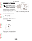
DRIVE HUBS
PRESSURE ARMS
IN OPEN POSITION
SLIDE DRIVE ROLL
ON DRIVE HUB
TRIANGULAR RING IN
UNLOCKED POSITION
TRIANGULAR RING IN
LOCKED POSITION
FIGURE AA.6
FIGURE AA.7
FIGURE AA.7a