


LF-72/74
F-14 F-14
Return to Section TOC Return to Section TOC Return to Section TOC Return to Section TOC
Return to Master TOC Return to Master TOC Return to Master TOC Return to Master TOC
577
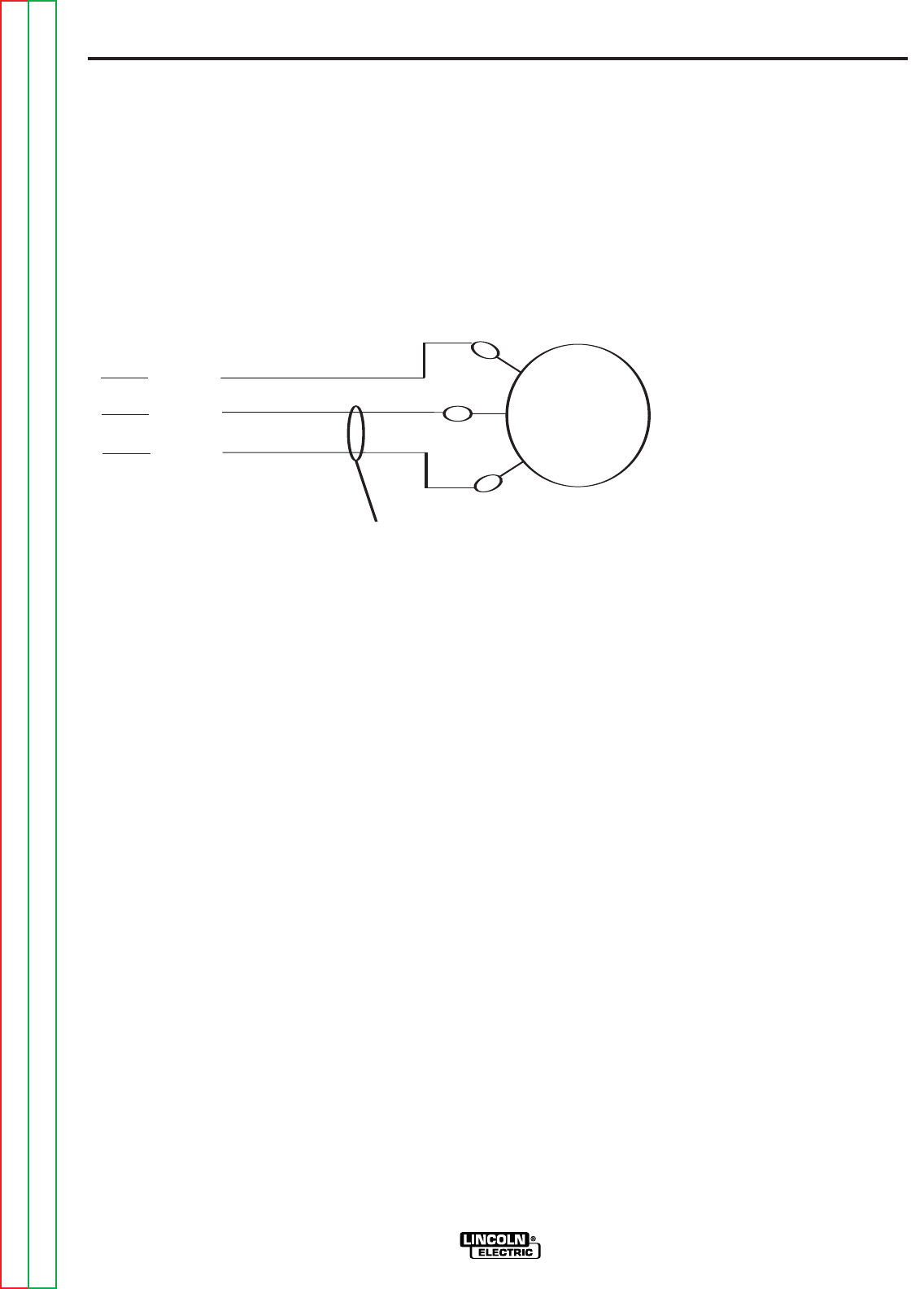
576
575
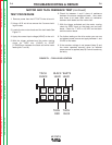
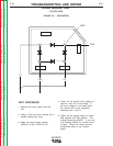
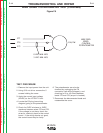
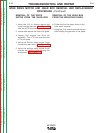
0 VDC MIN. WFS
5 VDC MIN. WFS
10K/2W
WIRE FEED
SPEED
CONTROL
POTENTIOMETER
TEST PROCEDURE
1. Remove the input power from the unit.
2. Using 5/16 nut driver remove the 5
screws holding the cover.
3. Apply the correct input voltage
(42VAC) to the LF72/LF74 unit.
4. Locate the P8 plug (see wiring
diagram) going to the potentiometer.
5. Check for 0VDC minimum to 5VDC
maximum between wires 575 and 576.
If the voltage is not there, check the
wires for continuity back to the control
board. If the wiring checks out good,
the control board may be faulty.
6. The potentiometer can also be
checked by unplugging the P8
connection (see wiring diagram), and
checking for 0 to 10k ohms between
leads 575 and 576 (as pot is located).
7. Reconnect the disconnected leads and
reassemble the cover.
TROUBLESHOOTING AND REPAIR
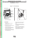
WIRE SPEED POTENTIOMETER TEST (Continued)
Figure F.5