


LF-72/74
F-12 F-12
Return to Section TOC Return to Section TOC Return to Section TOC Return to Section TOC
Return to Master TOC Return to Master TOC Return to Master TOC Return to Master TOC
TROUBLESHOOTING AND REPAIR
552A
552B
+
-
580
42
41
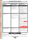
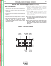
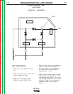
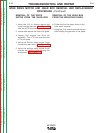
DIODE BRIDGE TEST
(continued)
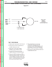
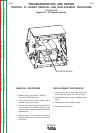
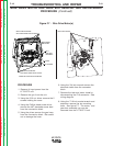
FIGURE F.4 – CONTACTOR
TEST PROCEDURE
1. Remove the input power from the
unit.
2. Using a 5/16 nut driver remove the 5
screws holding the cover.
3. Apply the correct input voltage
(42VAC) to the LF72/LF74 unit.
4. Check for the correct input voltage at
leads 41 and 42 on the bridge. If
the input voltage is not there check
the wiring back to the receptacle
assembly pins I and K.
5. Check for the proper output on leads
580 negative and 522 positive. The
voltage should be 59VDC. If you are
only reading 38VDC the control circuit
is open. Check the wiring and the
connections back to your control
board.