


LF-72/74
MAINTENANCE
DD-2 DD-2
Return to Section TOC Return to Section TOC Return to Section TOC Return to Section TOC
Return to Master TOC Return to Master TOC Return to Master TOC Return to Master TOC
MAINTENANCE
Safety Precautions
ELECTRIC SHOCK can kill.
• Do not touch electrically live parts
such as output terminals or inter-
nal wiring.
• When inching with gun trigger, electrode and
drive mechanism are “hot” to work and ground
and could remain energized several seconds
after the gun trigger is released.
• Turn OFF input power at welding power source
before installation or changing drive roll and/or
guide tubes.
• Welding power source must be connected to sys-
tem ground per the National Electrical Code or
any applicable local codes.
• Only qualified personnel should perform mainte-
nance work.
------------------------------------------------------------------------
WARNING
Observe all additional Safety Guidelines detailed
throughout this manual.
ROUTINE MAINTENANCE
• Clean and tighten all weld terminals.
• Inspect all weld cables, control cables, gun cables
and shielding gas hoses. Repair or replace as nec-
essary.
PERIODIC MAINTENANCE
• Clean drive roll grooves.
• Blow out or vacuum the inside of the feeder.
CALIBRATION SPECIFICATION
ELECTRIC SHOCK can kill.
• Do not touch electrically live parts.
• When inching with the gun trigger,
electrode, wire drive motor and
drive mechanism are "hot" to
work and ground and could
remain energized several seconds
after the gun trigger is released.
• Welding power source must be
connected to system ground per
the National Electrical Code or
any applicable local codes.
• Only qualified personnel should perform mainte-
nance work.
------------------------------------------------------------------------
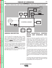
Calibration of the LF-74 may be required when the p.c.
board, potentiometer or motor is replaced or serviced.
Calibration matches the scale on the name plate to the
actual wire feed speed.
To verify the wire feed speed,
1. Assemble a .045 (1.2 mm) drive roll kit to the feed-
er.
2. Load .045 (1.2 mm) steel wire into the feeder.
3. Trim the wire to the end of the contact tip of the gun.
4. Adjust the WFS knob per the Table D.1.
TABLE D.1
5. Activate and hold the COLD FEED switch for 10
seconds.
6. Measure the length of wire extending from the con-
tact tip. The wire length shown in Table D.2.
TABLE D.2
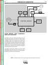
To calibrate the wire feed speed,
Tools required:
• 5/16" nut driver
• 3/4" open end wrench
• WFS meter or RPM meter
• Shorting plug. The shorting plug shorts pins 1 and 5
of connector J2 on the p.c. board. J2 is a 6 pin
molex.
1. Turn off power to the LF-74 and welding power
source.
2. Disconnect the electrode lead from the feed plate
and from the welding power source.
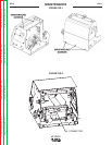
3. Remove the wraparound from the LF-74,
See
Figure D.1.
4. Turn on power to the LF-74 and welding power
source.
5. Adjust the WFS knob per the Table D.1.
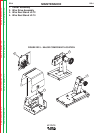
6. Insert the shorting plug into the control p.c. board J2.
(shorts pins 1 and 5.)
See Figure D.2.
7. Wait a minimum of 1 second.
8. Remove the shorting plug.
9. Connect J2 of the harness to p.c. board.
10. Turn off power to the LF-74 and welding power
source.
11. Assemble the wraparound.
12. Connect the electrode lead.
WARNING
MODEL
K2426-1, K2426-1
K2426-3
MODEL
K2426-1, K2426-1
K2426-3
WIRE LENGTH
50 inches ± 5 inches (1270 mm ± 127mm)
25 inches ± 2.5 inches (635 mm ± 64 mm)
WFS knob setting
400
200