


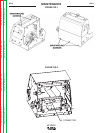

LF-72/74
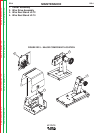
THEORY OF OPERATION
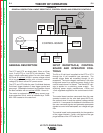
DRIVE MOTOR, TACH FEEDBACK
AND GAS SOLENOID
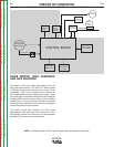
The leads to the drive motor, gas solenoid and the
tach (hall effect device LF-74 and LF-72 above codes
11290) are brought into the control box via the 14 pin
receptacle. This 14 pin receptacle also houses the
gun trigger leads and the voltage sense leads. When
the gun trigger is activated the control board energizes
the gas solenoid, the wire drive motor and the welding
power source. The control board receives a tach feed-
back signal and adjusts the motor armature voltage to
match the preset wire feed speed.
The control board also monitors the drive motor
amperage and will shut down the wire drive for 30 to
60 seconds to allow the motor to cool if the amperage
exceeds 3.75 amps for an extended time.
E-3 E-3
Return to Section TOC Return to Section TOC Return to Section TOC Return to Section TOC
Return to Master TOC Return to Master TOC Return to Master TOC Return to Master TOC
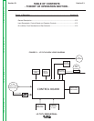
NOTE: Unshaded areas of Block Logic Diagram are the subject of discussion.
FIGURE E.3 – DRIVE MOTOR, TACH FEEDBACK AND GAS SOLENOID
14 PIN
INPUT CABLE
RECEPTACLE
24/42 VAC
CONTROL BOARD
WIRE FEED
SPEED POT.
TRIGGER
INTERLOCK
2-STEP
COLD FEED
GAS PURGE
OPTIONAL
BURNBACK
TIMER
OPTIONAL
REMOTE
VOLTAGE
CONTROL
GAS
SOLENOID
3.75 AMP
OVERLOAD
PROTECTION
WIRE DRIVE
RECEPTACLE
WIRE
DRIVE
MOTOR
T
ACK
To Gun Trigger