


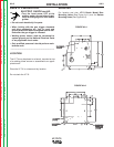
LF-72/74
INSTALLATION
AA-11 AA-11
Return to Section TOC Return to Section TOC Return to Section TOC Return to Section TOC
Return to Master TOC Return to Master TOC Return to Master TOC Return to Master TOC
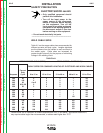
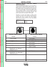
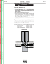
Gun Receiver For use With
Bushing
K1500-1 K466-1 Lincoln gun connectors;
Innershield and Subarc guns)
K1500-2 K466-2, K466-10 Lincoln gun
connectors; Magnum 200/300/400
guns and compatible with Tweco®
#2 - #4)
K1500-3 K1637-7 Lincoln gun connectors;
Magnum 550 guns and compatible
with Tweco® #5)
K1500-4 K466-3 Lincoln gun connectors;
compatible with Miller® guns.)
K1500-5 (Compatible with Oxo® guns.)
K489-7 ( Lincoln Fast-Mate guns.)
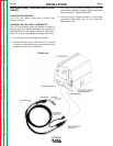
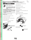
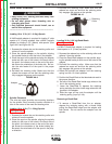
7. Disconnect the shielding gas hose from the gun
bushing, if required.
8. Connect the shielding gas hose to the new gun
bushing, if required.
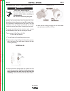
9. Rotate the gun bushing until the thumb screw hole
aligns with the thumb screw hole in the feed plate.
Slide the gun receiver bushing into the wire drive
and verify the thumb screw holes are aligned.
10. Tighten the socket head cap screw.
11. Insert the welding gun into the gun bushing and
tighten the thumb screw.
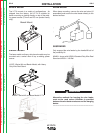
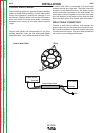
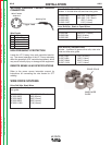
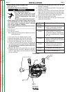
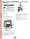
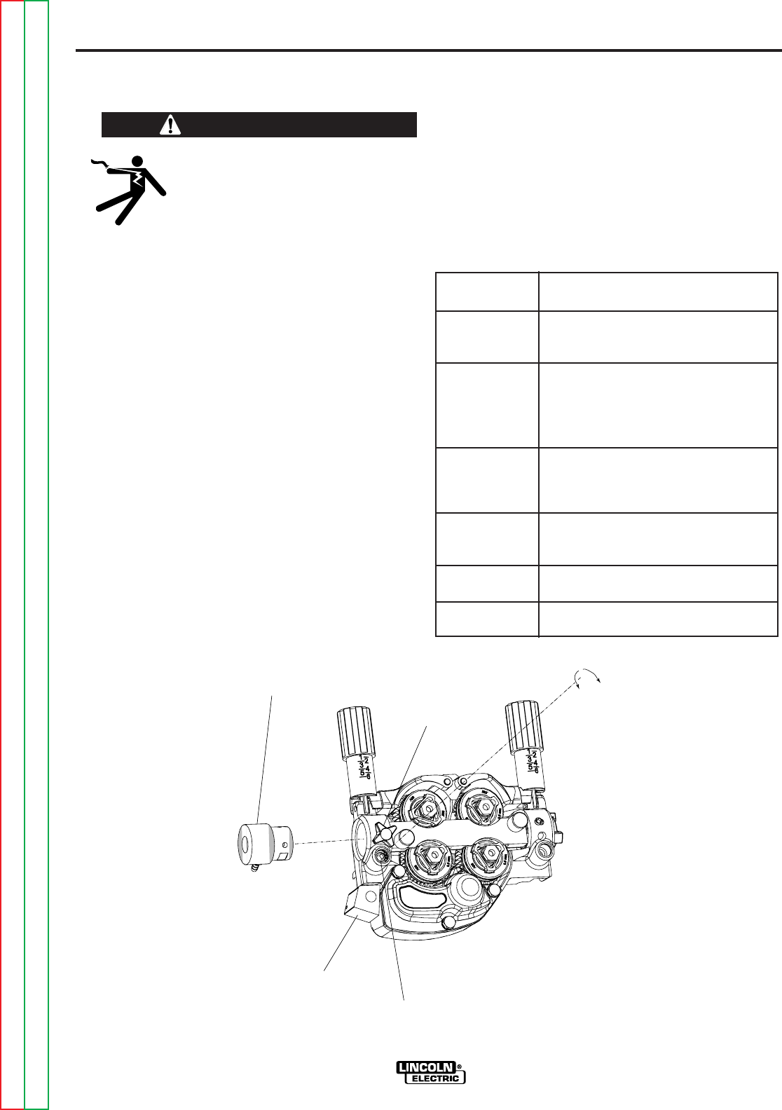
WIRE DRIVE CONFIGURATION
(See Figure AA.5)
Changing the Gun Receiver Bushing
ELECTRIC SHOCK can kill.
• Turn the input power OFF at the
welding power source before instal-
lation or changing drive rolls and/or
guides.
• Do not touch electrically live parts.
• When inching with the gun trigger, electrode and
drive mechanism are "hot" to work and ground
and could remain energized several seconds
after the gun trigger is released.
• Only qualified personnel should perform mainte-
nance work.
------------------------------------------------------------------------
Tools required:
• 1/4" hex key wrench
Note: Some gun bushings do not require the use of
the thumb screw.
1. Turn power off at the welding power source.
2. Remove the welding wire from the wire drive.
3. Remove the thumb screw from the wire drive.
4. Remove the welding gun from the wire drive.
5. Loosen the socket head cap screw that holds the
connector bar against the gun bushing.
Important:
Do not attempt to completely remove the sock-
et head cap screw.
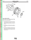
6. Remove the outer wire guide, and push the gun
bushing out of the wire drive. Because of the pre-
cision fit, light tapping may be required to remove
the gun bushing.
WARNING
GUN RECEIVER BUSHING
CONNECTOR
BAR
SOCKET
HEAD CAP
SCREW
THUMB
SCREW
LOOSEN
CAP
SCREW
TIGHTEN
CAP
SCREW
FIGURE AA.5