


LF-72/74
F-8 F-8
Return to Section TOC Return to Section TOC Return to Section TOC Return to Section TOC
Return to Master TOC Return to Master TOC Return to Master TOC Return to Master TOC
TROUBLESHOOTING & REPAIR
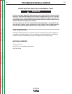
TEST PROCEDURE
1. Remove power from the LF72/LF74 wire drive unit.
2. Using a 5/16 nut driver remove the 5 screws hold-
ing the case.
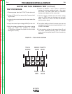
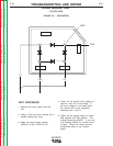
3. Locate the two motor leads and the tach leads See
Figure F.1.
4. Apply the correct input voltage (42VAC) to the unit.
5. With the trigger activated and the motor running
check for 1VDC min. (210HZ) to 31VDC
(1.75KHZ)max. between the black and white motor
leads (pins 7 and 8).
6. Check for between 1 and 2 ohms of resistance
between the above mentioned leads. Also make
sure there is at least 500k ohms of resistance
between both leads and the motor shell.
7. With the trigger activated and the motor running
check for 5VDC input on the black and red tach
leads. Check for .7 VDC to .85 VDC on the black
and blue return leads.
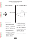
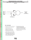
8. For further testing on the drive motor you can use
an isolated power source and apply between 1 and
31VDC to the leads.
9. If the armature voltage is not present (step 5) and
the motor operates normally when an isolated
power source is applied (step 8) Control board may
be faulty.
1
23
4
8
7
5
6
TACH
BLACK
BLACK
LEAD
WHITE
LEAD
TACH
RED
TACH
BLUE
FIGURE F.1 – TACH LEAD LOCATION
MOTOR AND TACH FEEDBACK TEST (continued)