


LF-72/74
INSTALLATION
A-7 A-7
Return to Section TOC Return to Section TOC Return to Section TOC Return to Section TOC
Return to Master TOC Return to Master TOC Return to Master TOC Return to Master TOC
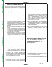
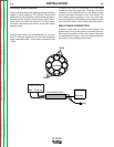
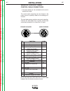
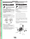
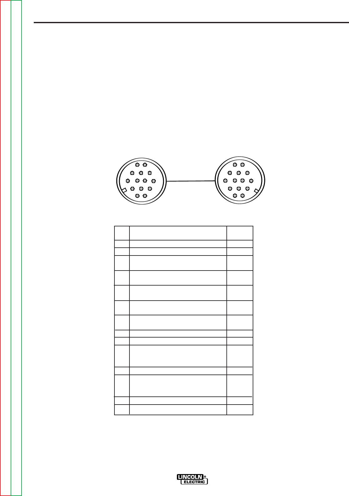
ANALOG CONTROL CABLE
CONTROL CABLE CONNECTIONS
• All control cables can be connected end to end to
extend their length.
The control cable connecting the wire feeder to the
power source is specially made for the welding envi-
ronment.
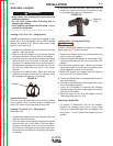
The wire feeder power requires overcurrent protection.
Connect the wire feeder only to power sources with
overcurrent protection of no more than 15 amps.
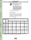
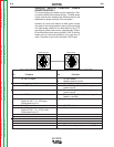
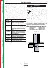
PIN FUNCTION LEAD#
A Unused -------
B Reserved -------
C Welding Output Control 2
(trigger from feeder)
D Welding Output Control 4
(trigger from feeder)
E Remote Voltage Control 77
(“+” supply from feeder or remote)
F Remote Voltage Control 76
(control signal from feeder or remote)
G Remote Voltage Control 75
(“-” supply from feeder or remote)
H Reserved
I 42 VAC 41
J Reserve for Future Use.
K 42 VAC 42
L Reserve for Future Use.
M Unused -------
N Electrode voltage from feeder 67
Do not use more than 100 ft (30.5 m) of control cable
between the wire feeder and power source.
A
I
H
G
B
F
E
D
C
J
K
N
M
L
A
B
C
D
I
E
F
G
H
J
K
L
M
N
POWER SOURCE WIRE FEEDER