


LF-72/74
TROUBLESHOOTING AND REPAIR
F-20 F-20
Return to Section TOC Return to Section TOC Return to Section TOC Return to Section TOC
Return to Master TOC Return to Master TOC Return to Master TOC Return to Master TOC
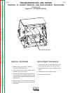
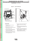
WIRE DRIVE MOTOR AND GEAR BOX REMOVAL AND REPLACEMENT
PROCEDURE
(Continued)
REPLACEMENT PROCEDURES
1. Line up the gear box with the 4 holes on
the panel. Replace and tighten the four
1/4-20 x 1/2 in. hex head bolts.
2. Insert the drive motor through the panel
and gear box. Line up and tighten the
three M6 x 1.00 in. Phillips pan head
screws.
3. Replace the drive gear and secure in
place using the screw and lock washer
previously removed.
4. Replace the drive rolls and secure the
secure locking rings.
5. Replace the gear box cover and secure
with the 1/4-20 hex head screws.
6. Feed the gas hose, and the # 67 lead
through the notch on the panel. Feed the
P10 plug through the center panel. Align
and mount and tighten the panel using
the six lock washers and bolts previously
removed.
7. Plug the P10 plug into the wiring
harness.
8. Using the Phillips head screw driver
connect the #67 electrode sense lead to
the connector block.
9. Using the 3/4 in. wrench connect the
electrode lead to the connector block.
10. Connect the gas hose.
11. Install the cover using the five screws.
12. Connect the gun.