


LF-72/74
INSTALLATION
A-5 A-5
Return to Section TOC Return to Section TOC Return to Section TOC Return to Section TOC
Return to Master TOC Return to Master TOC Return to Master TOC Return to Master TOC
SAFETY PRECAUTION
ELECTRIC SHOCK can kill.
• Only qualified personnel should
perform this installation.
• Turn off the input power to the
power source at the disconnect
switch or fuse box before working
on this equipment. Turn off the
input power to any other equipment
connected to the welding system at
the disconnect switch or fuse box
before working on this equipment.
• Do not touch electrically hot parts.
----------------------------------------------------------------------
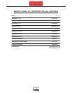
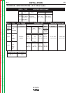
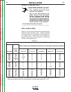
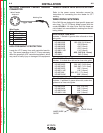
** Tabled values are for operation at ambient temperatures of 40°C and below. Applications above 40°C
may require cables larger than recommended, or cables rated higher than 75°C.
Amperes
200
200
225
225
250
250
250
250
300
325
350
400
400
500
Percent
Duty
Cycle
60
100
20
40 & 30
30
40
60
100
60
100
60
60
100
60
200 to 250 Ft.
61 to 76 m
1/0
1/0
1/0
1/0
1/0
1/0
1/0
1/0
2/0
3/0
3/0
4/0
4/0
4/0
150 to 200 Ft.
48 to 61 m
1
1
1
1
1
1
1
1
1/0
2/0
2/0
3/0
3/0
3/0
100 to 150 Ft.
31 to 48 m
2
2
2
2
2
1
1
1
1
2/0
2/0
2/0
3/0
3/0
50 to 100Ft.
15 to 31 m
2
2
3
3
3
2
1
1
1
2/0
1/0
2/0
3/0
2/0
0 to 50 Ft.
0 to 15 m
2
2
4 or 5
3
3
2
1
1
1
2/0
1/0
2/0
3/0
2/0
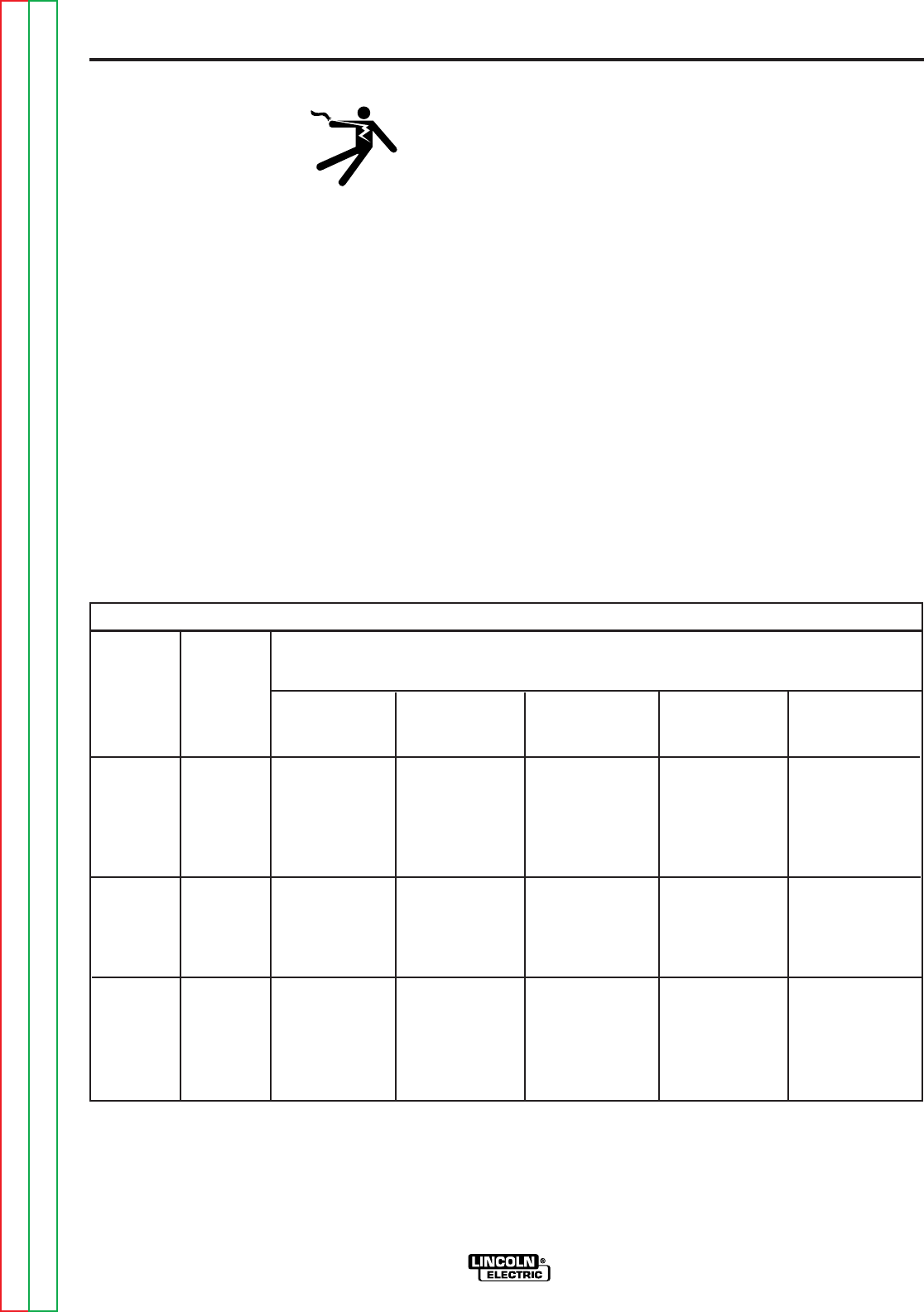
RECOMMENDED CABLE SIZES (RUBBER COVERED COPPER - RATED 75°C)**
CABLE SIZES FOR COMBINED LENGTHS OF ELECTRODE AND WORK CABLES
WELD CABLE SIZES
Table A.1 has the copper cable sizes recommended for
different currents and duty cycles. Lengths stipulated
are the distance from the welder to work and back to
the welder again. Cable sizes are increased for
greater lengths primarily for the purpose of minimizing
voltage in the welding circuit.
TABLE A.1