


LF-72/74
INSTALLATION
A-11 A-11
Return to Section TOC Return to Section TOC Return to Section TOC Return to Section TOC
Return to Master TOC Return to Master TOC Return to Master TOC Return to Master TOC
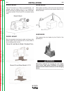
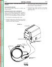
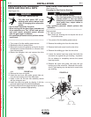
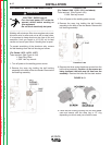
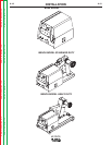
WIRE DRIVE CONFIGURATION
(See Figure A.5)
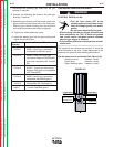
Changing the Gun Receiver Bushing
ELECTRIC SHOCK can kill.
• Turn the input power OFF at the dis-
connect switch or fuse box before
attempting to connect or disconnect
input power lines, output cables or
control cables.
• Only qualified personnel should perform this
installation.
------------------------------------------------------------------------
Tools required:
• 1/4" hex key wrench
Note: Some gun bushings do not require the use of
the thumb screw.
1. Turn power off at the welding power source.
2. Remove the welding wire from the wire drive.
3. Remove the thumb screw from the wire drive.
4. Remove the welding gun from the wire drive.
5. Loosen the socket head cap screw that holds the
connector bar against the gun bushing. Important:
Do not attempt to completely remove the socket
head cap screw.
6. Remove the outer wire guide, and push the gun
bushing out of the wire drive. Because of the preci-
sion fit, light tapping may be required to remove the
gun bushing.
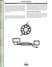
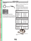
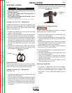
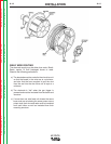
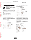
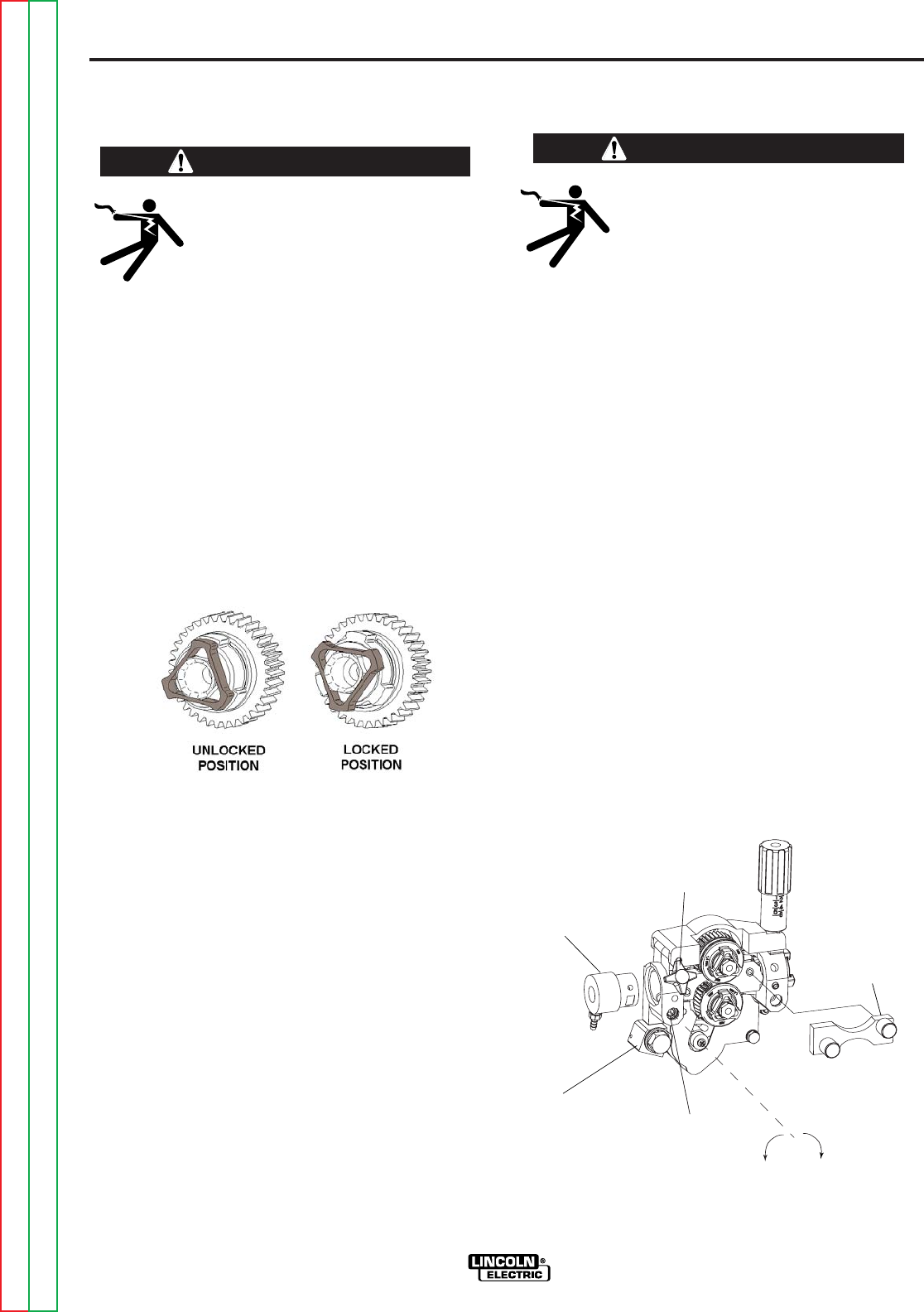
PROCEDURE FOR CHANGING
DRIVE AND IDLE ROLL SETS
(See Figure A.4 )
ELECTRIC SHOCK can kill.
• Turn the input power OFF at the
welding power source before instal-
lation or changing drive rolls and/or
guides.
• Do not touch electrically live parts.
• When inching with the gun trigger, electrode and
drive mechanism are "hot" to work and ground
and could remain energized several seconds
after the gun trigger is released.
• Only qualified personnel should perform mainte-
nance work.
-----------------------------------------------------------------------
-
1. Turn power off at the welding power source.
2. Release the idle roll pressure arm.
3. Remove the outer wire guide by turning the knurled
thumbscrews counter-clockwise to unscrew them
from the feed plate.
4. Rotate the triangular lock and remove the drive
rolls.
FIGURE A.4
5. Remove the inner wire guide.
6. Insert the new inner wire guide, groove side out,
over the two locating pins in the feed plate.
7. Install a drive roll on each hub assembly secure
with the triangular lock.
8. Install the outer wire guide by aligning it with the
pins and tightening the knurled thumbscrews.
9. Close the idle arm and engage the idle roll pressure
arm. Adjust the pressure appropriately.
WARNING
WARNING
GUN RECEIVER BUSHING
LOOSEN TIGHTEN
THUMB SCREW
OUTER WIRE GUIDE
SOCKET HEAD
CAP SCREW
CONNECTOR BLOCK
FIGURE A.5