


LF-72/74
INSTALLATION
AA-14 AA-14
Return to Section TOC Return to Section TOC Return to Section TOC Return to Section TOC
Return to Master TOC Return to Master TOC Return to Master TOC Return to Master TOC
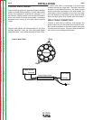
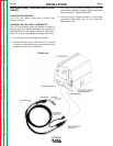
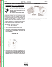
SHIELDING GAS CONNECTION
CYLINDER may explode if damaged.
• Keep cylinder upright and chained to
support.
• Keep cylinder away from areas
where it may be damaged.
• Never lift welder with cylinder attached.
• Never allow welding electrode to touch cylinder.
• Keep cylinder away from welding or other live
electrical circuits.
------------------------------------------------------------------------
BUILD-UP OF SHIELDING GAS may
harm health or kill.
• Shut off shielding gas supply when
not in use.
SEE AMERICAN NATIONAL STANDARD Z-49.1,
"SAFETY IN WELDING AND CUTTING" PUB-
LISHED BY THE AMERICAN WELDING SOCIETY.
------------------------------------------------------------------------
Maximum inlet pressure is 100 psi. (6.9 bar.)
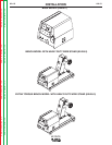
Install the shielding gas supply as follows:
1. Secure the cylinder to prevent it from falling.
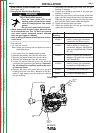
2. Remove the cylinder cap. Inspect the cylinder
valves and regulator for damaged threads, dirt, dust,
oil or grease. Remove dust and dirt with a clean
cloth. DO NOT ATTACH THE REGULATOR IF OIL,
GREASE OR DAMAGE IS PRESENT! Inform your
gas supplier of this condition. Oil or grease in the
presence of high pressure oxygen is explosive.
3. Stand to one side away from the outlet and open the
cylinder valve for an instant. This blows away any
dust or dirt which may have accumulated in the
valve outlet.
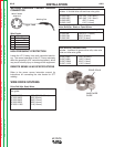
4. Attach the flow regulator to the cylinder valve and
tighten the union nut(s) securely with a wrench.
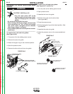
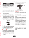
Note: if connecting to 100% CO
2
cylinder, insert reg-
ulator adapter between regulator and cylinder valve.
If adapter is equipped with a plastic washer, be sure
it is seated for connection to the CO
2
cylinder.
5. Attach one end of the inlet hose to the outlet fitting
of the flow regulator. Attach the other end to the
welding system shielding gas inlet. Tighten the
union nuts with a wrench.
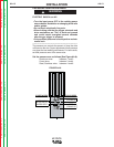
6. Before opening the cylinder valve, turn the regulator
adjusting knob counterclockwise until the adjusting
spring pressure is released.
7. Standing to one side, open the cylinder valve slowly
a fraction of a turn. When the cylinder pressure gage
stops moving, open the valve fully.
8. The flow regulator is adjustable. Adjust it to the flow
rate recommended for the procedure and process
being used before making a weld.