


A-5
INSTALLATION
IDEALARC SP-250
A-5
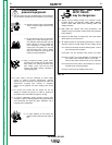
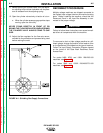
11. Before opening the cylinder valve, turn the regula-
tor adjusting knob counter clockwise until the pres-
sure is released from the adjusting spring.
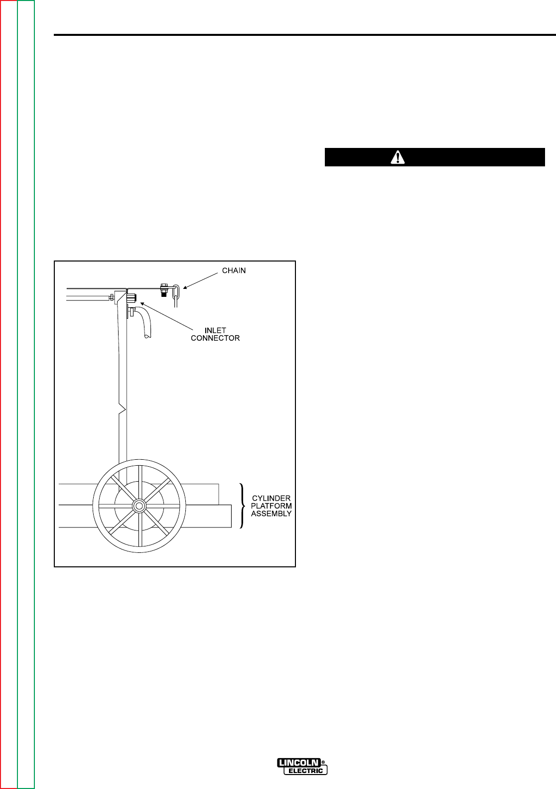
12. Open the cylinder valve slowly a fraction of a turn.
a. When the cylinder pressure gage pointer stops
moving, open the valve fully.
NEVER STAND DIRECTLY IN FRONT OF OR
BEHIND THE FLOW REGULATOR WHEN OPENING
THE CYLINDER VALVE. ALWAYS STAND TO ONE
SIDE.
13. Adjust the flow regulator for the flow rate recom-
mended for the procedure and process being used
before making the weld.
FIGURE A.4 - Shielding Gas Supply Connections
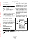
RECONNECT PROCEDURE
Multiple voltage machines are shipped connected to
the highest input voltage listed on the machine's rating
plate. Before installing the machine, check that the
Reconnect Panel in the Input Box Assembly is con-
nected for the proper voltage.
Failure to follow these instructions can cause immedi-
ate failure of components within the machine.
____________________________________
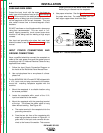
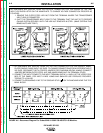
To reconnect a dual or triple voltage machine to a dif-
ferent voltage, change the position of the leads or links
on the Reconnect Panel based on the type of machine.
Follow The Input Supply Connection Diagram located
on the inside of the Case Back Reconnect Panel
Access Door.
For codes 9402, 9723, and 10001 208/230/1/60
machines, see Figure A.5.
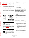
For codes 9546 and 10002 230/460/575/1/60
machines, see Figure A.6.
Return to Section TOC Return to Section TOC Return to Section TOC Return to Section TOC
Return to Master TOC Return to Master TOC Return to Master TOC Return to Master TOC
CAUTION