


Return to Section TOC Return to Section TOC Return to Section TOC Return to Section TOC
Return to Master TOC Return to Master TOC Return to Master TOC Return to Master TOC
F-15
TROUBLESHOOTING & REPAIR
F-15
IDEALARC SP-250
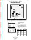
TEST PROCEDURE
The ON/OFF POWER SWITCH will be
"hot" during these tests.
__________________________
NOTE: Secondary voltages will vary pro-
portionably with the primary input volt-
age.
1. Disconnect the main input power
supply to the machine.
2. Remove the Case Top and Side
Panels with a 5/16" nut driver.
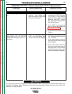
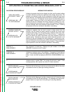
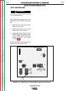
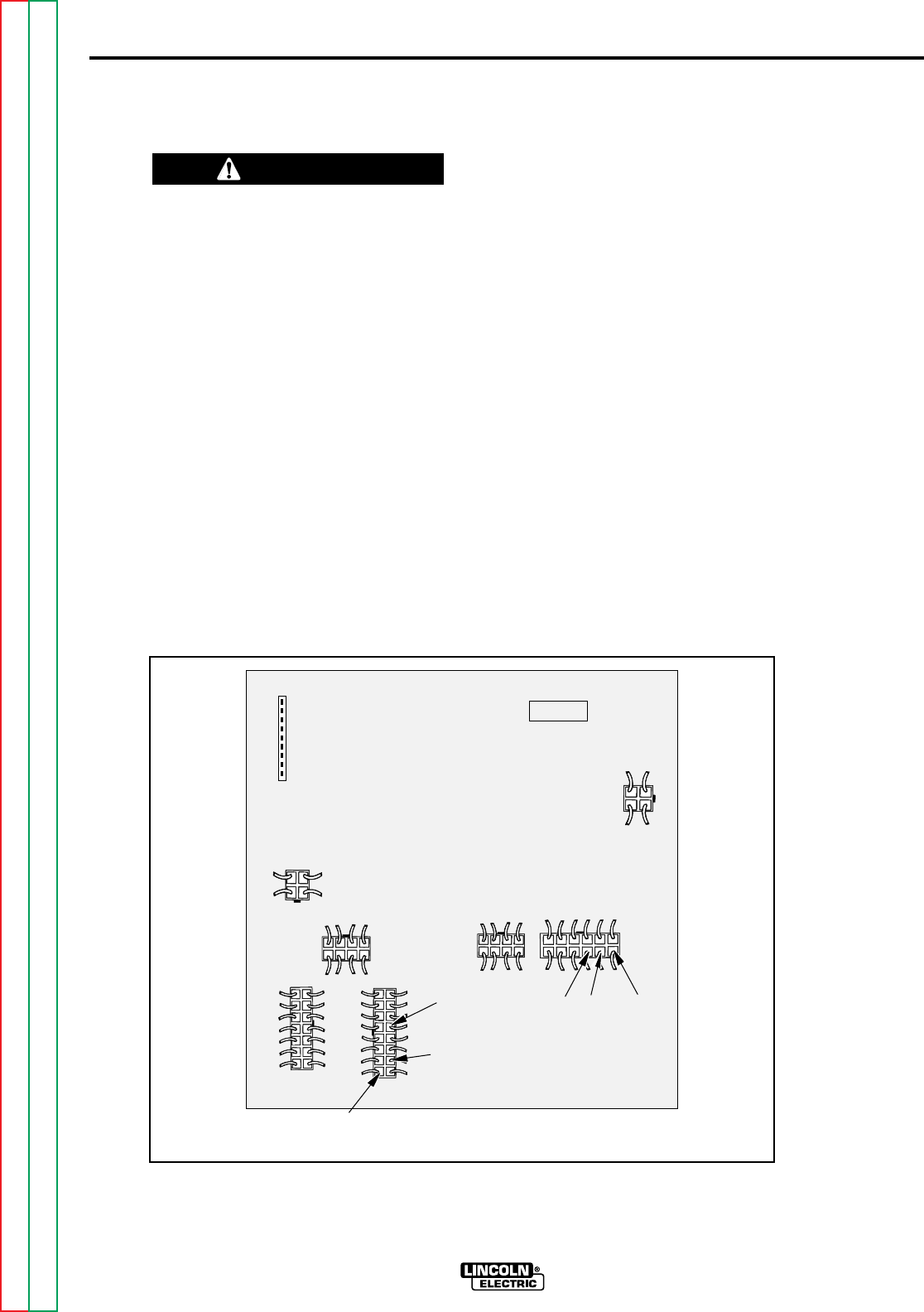
3. Locate Plug J3 and Plug J6 on the
G2252 Control PC Board or Plug J3
on the G1992 (Code 9402 only)
Control PC Board. See Figures
F.1A and F.1B.
NOTE: The location of Plugs may vary
depending on the machine code.
FIGURE F.1A - G2252 Control PC Board Main Transformer Test Points.
MAIN TRANSFORMER TEST
G2252
SP-250 CONTROL
J2
J7
J4
J5
J6
J9
J3
J8
#202
(1J3)
#204A
(2J3)
#203
(3J3)
#206
(4J6)
#209
(7J6)
#208
(16J6)
WARNING