


F-23
TROUBLESHOOTING & REPAIR
F-23
IDEALARC SP-250
TEST PROCEDURE
1. Disconnect main AC input power to
the machine.
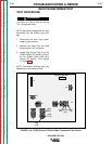
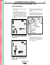
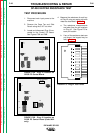
2. Disconnect Molex Plugs J3 and J6
from the G2252 Control Board or
remove Plug J3 from G1992 Control
Board (Code 9402 only)
See Figures F.5A and F.5B.
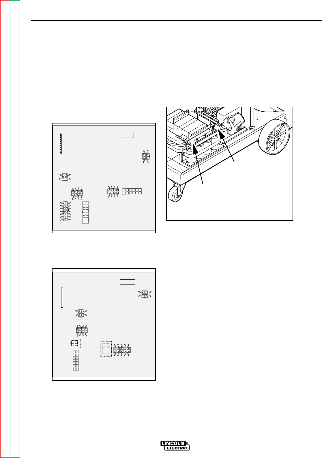
FIGURE F.5A - Control Board Molex
Plug Locations for G2252 PC Control
Board.
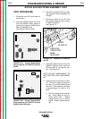
FIGURE F.5B - Control Board Molex
Plug Locations for G1992 PC Control
Board (Code 9402 only.)
3. Test with an Analog Volt-Ohm meter
that capacitors have completely dis-
charged.
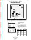
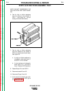
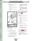
4. Disconnect leads X2 and X3 from
the negative capacitor bank using a
fi" open end wrench.
See Figure F. 6.
FIGURE F.6 - Location of Leads X2
and X3.
5. Separate leads X2 and X3 from the
negative capacitor bank buss bar.
Be sure there is no electrical con-
tact. See Figure F6.
NOTE: DO NOT DISASSEMBLE THE
SCR RECTIFIER HEAT SINK ASSEM-
BLY.
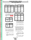
6. Construct the circuit shown in Figure
F.8. One 6-volt lantern battery can
be used. R1 and R2 resistor values
are ±10%. Set voltmeter scale low,
at approximately 0-5 volts or 5-10
volts.
a. Test the voltage level of the bat-
tery. Short leads (A) and (C).
Close switch SW-1. Battery
voltage should be 4.5 volts or
higher. If lower, replace the bat-
tery.
ACTIVE SCR RECTIFIER ASSEMBLY TEST
Return to Section TOC Return to Section TOC Return to Section TOC Return to Section TOC
Return to Master TOC Return to Master TOC Return to Master TOC Return to Master TOC
SP-250 CONTROL
G2252
J7
J4
J5
J6
J9
J3
J8
J2
SP-250 CONTROL
J7
J4
J5
J3
J6
J9
J8
G1992
J2
LEADS
X2 AND X3
NEGATIVE
CAPACITOR
BANK
BUSS BAR