


B-5
OPERATION
B-5
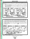
CONTROLS AND SETTINGS
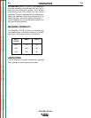
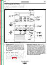
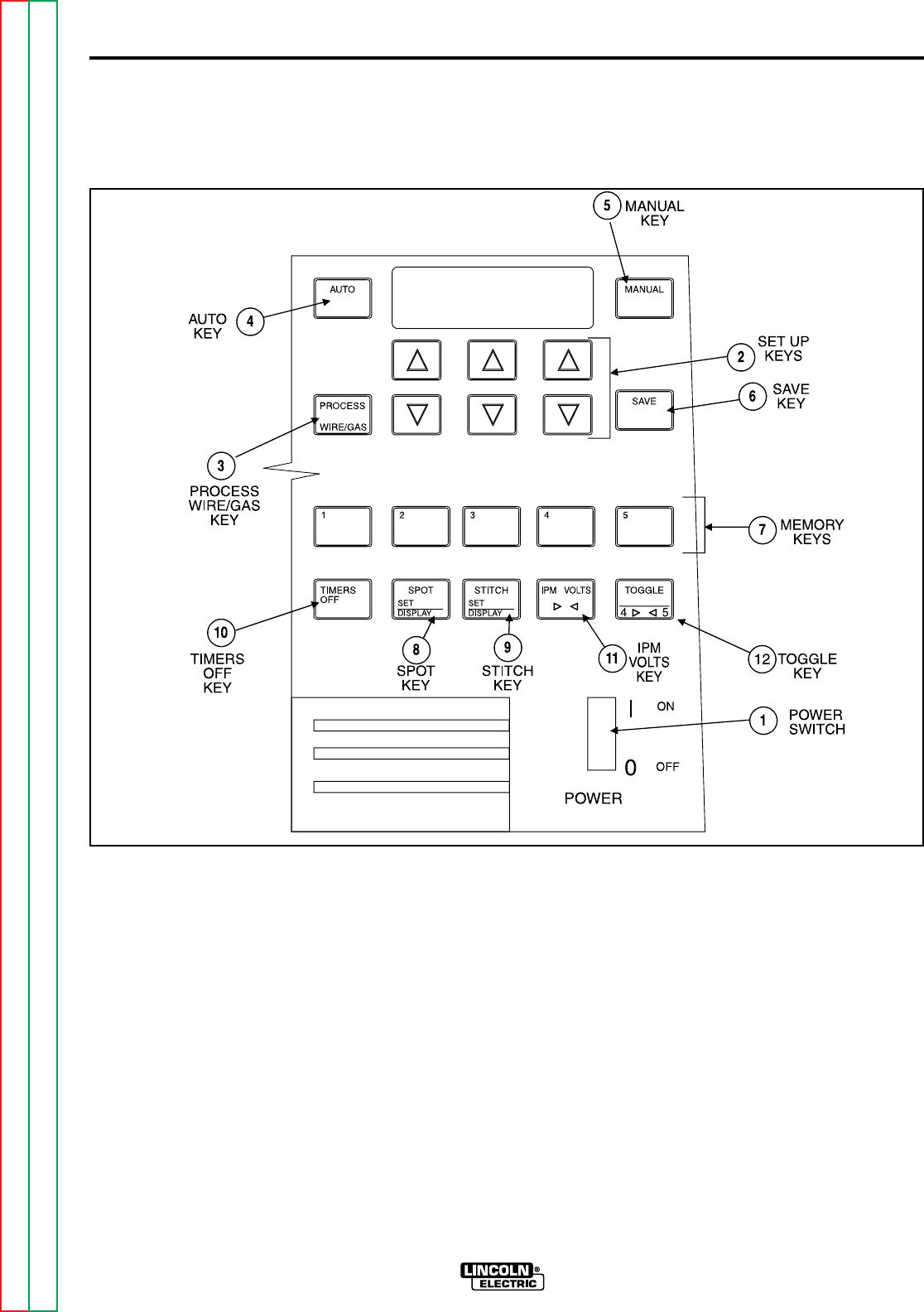
All operator controls are located on the Front Panel
Keypad/Nameplate. See Figure B.1 for the location of
each control.
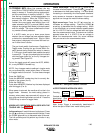
FIGURE B.1 - SP-250 Control Panel Keys
1. POWER SWITCH: Toggle switch to turn input
power ON and OFF. When the switch is in the ON
position the red LED backlighting of the LCD dis-
play lights and alphanumeric characters appear.
The welding setup in operation when the power
was shut off or disconnected is displayed when
power is restored.
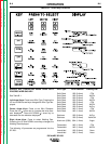
2. SET UP ARROW KEYS: Press keys to
change the display selection directly above the
keys. See Figure B.1. Function of arrow keys
change depending on PROCESS KEY being used.
For function of arrow keys, refer to each process or
procedure. See Table B.1 for summary of arrow
key operation.
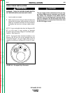
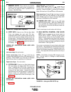
3. PROCESS WIRE/GAS KEY: Press key to
display the Wire Type, Wire Diameter, and Welding
Gas. Each combination of wire and gas dictates a
unique relationship between the wire feed speed
and the arc voltage. The SP-250 uses this unique
relationship, along with the metal thickness, to set
the proper values for wire feed speed and arc volt-
age. Therefore, it is very important that the wire
type, wire diameter, and welding gas displayed
match the actual wire type, wire diameter, and
welding gas being used for the weld.
IDEALARC SP-250
Return to Section TOC Return to Section TOC Return to Section TOC Return to Section TOC
Return to Master TOC Return to Master TOC Return to Master TOC Return to Master TOC