


F-26
TROUBLESHOOTING & REPAIR
F-26
IDEALARC SP-250
TEST PROCEDURE
1. Disconnect main input power to the
machine.
2. Remove the Case Top and Side
Panels using the 5/16" nut driver.
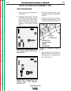
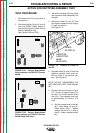
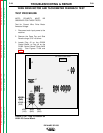
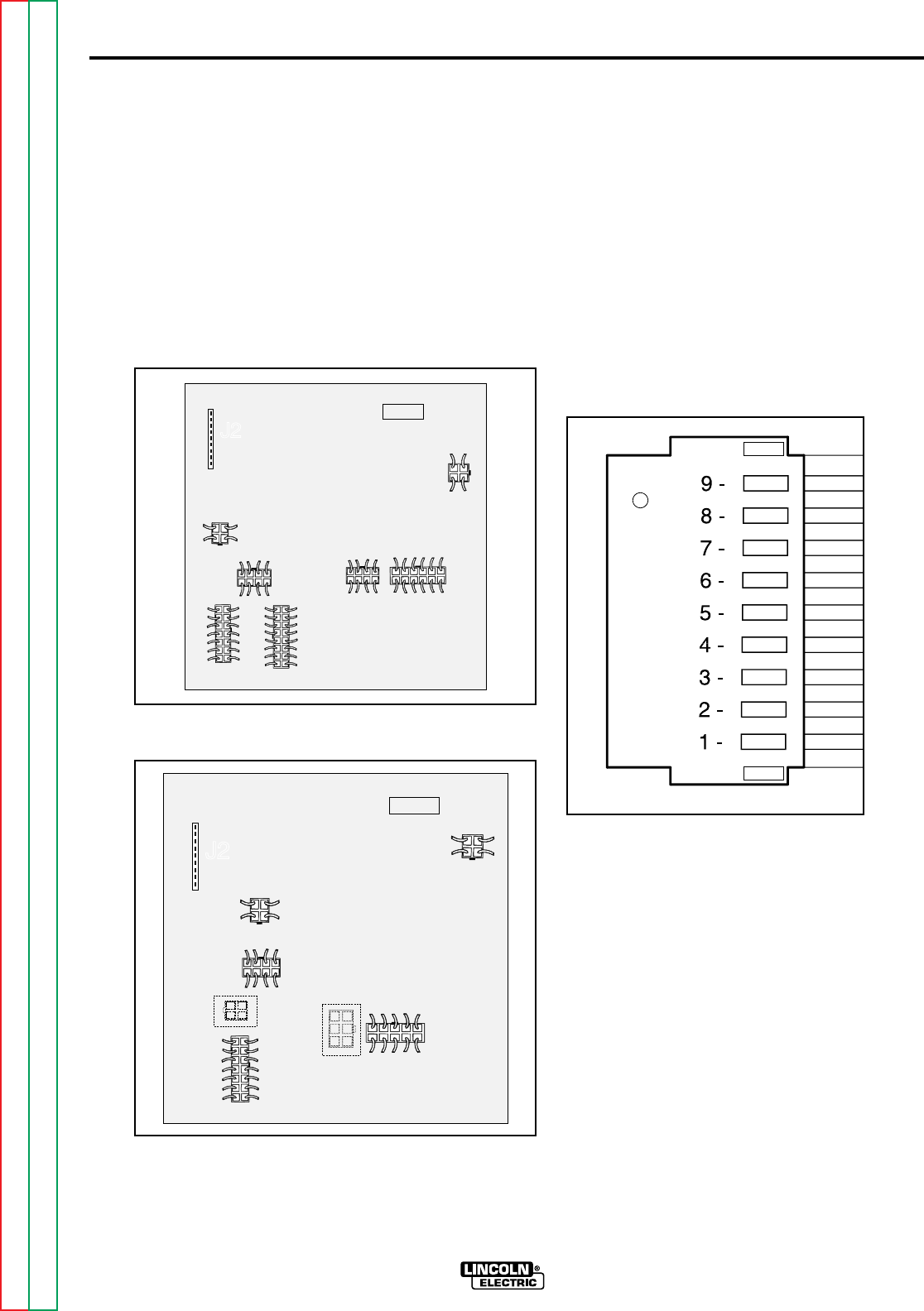
3. Locate and disconnect Plug J2 con-
nected to the Control PC Board.
See Figures F.8A and F8B.
FIGURE F.8A - Plug J2 Location on
G2252 PC Control Board.
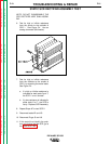
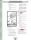
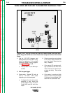
FIGURE F.8B - Plug J2 Location on
G1992 PC Control Board (Code 9402
only).
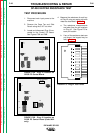
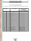
4. Measure the resistance of each key
at Plug J2 using an analog volt-ohm
meter as described in Table F.1.
a. The resistance measurements
are taken from the pin locations
on Plug J2. See Figure F.9 for
each pin location.
b. If any of the resistance tests are
not correct, the keypad may be
faulty. Replace.
FIGURE F.9 - Plug J2 Test Points.
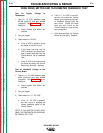
SP-250 KEYPAD RESISTANCE TEST
Return to Section TOC Return to Section TOC Return to Section TOC Return to Section TOC
Return to Master TOC Return to Master TOC Return to Master TOC Return to Master TOC
G2252
SP-250 CONTROL
J2
J7
J4
J5
J6
J9
J3
J8
SP-250 CONTROL
J2
J7
J4
J5
J3
J6
J9
J8
G1992