


Return to Section TOC Return to Section TOC Return to Section TOC Return to Section TOC
Return to Master TOC Return to Master TOC Return to Master TOC Return to Master TOC
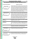
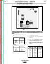
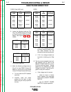
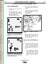
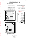
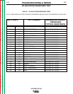
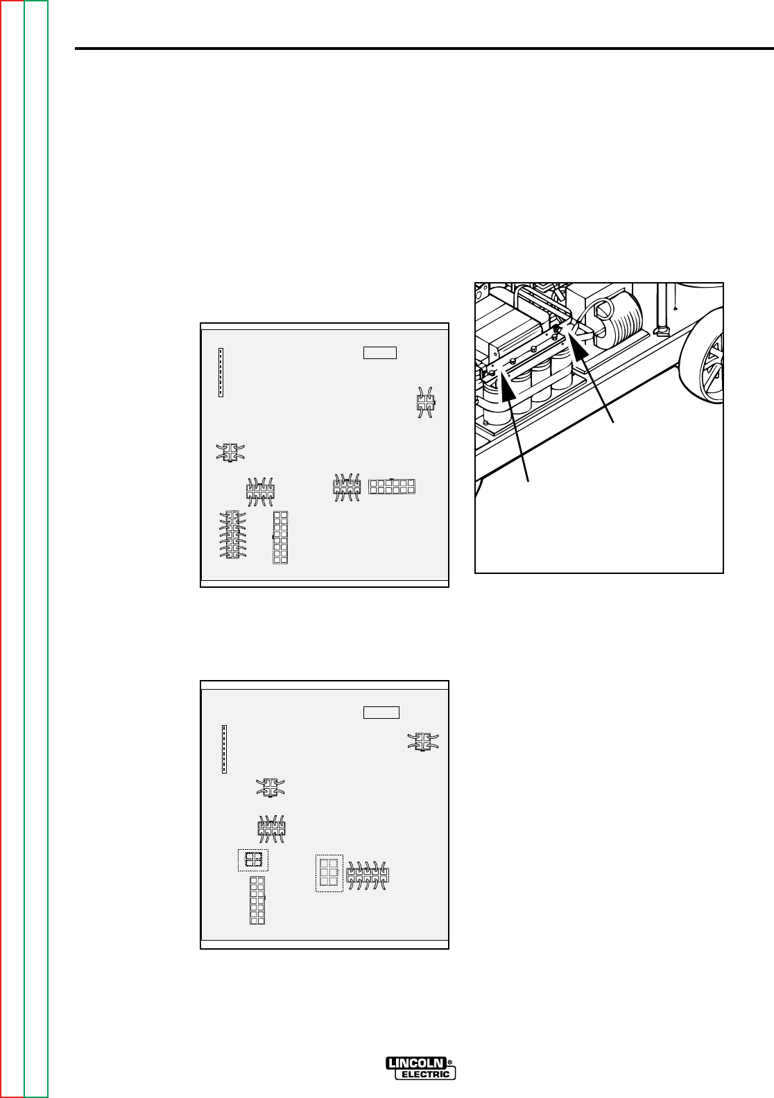
FIGURE F.2B - Remove Plug J3 to
Perform Static SCR Rectifier
Assembly Test.
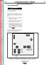
TEST PROCEDURE
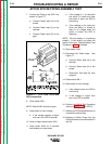
1. Disconnect main AC input power to
the machine.
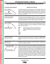
2. Disconnect Plugs J3 and J6 from
the G2252 Control Board or remove
Plug J3 from the G1992 Control
Board (Code 9402 only.) This elec-
trically isolates the SCR bridge
assembly. See Figures F.2A and
F.2B.
FIGURE F.2A - Remove Plugs J3 and
J6 to Perform Static SCR Rectifier
Assembly Test.
3. Test with an Analog Volt-Ohm meter
that capacitors have completely dis-
charged.
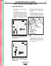
4. Disconnect leads X2 and X3 from
the negative capacitor bank using a
fi" open end wrench. See Figure F.3.
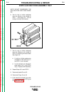
FIGURE F.3 - Location of Leads X2
and X3.
5. Separate leads X2 and X3 from the
negative capacitor bank buss bar.
Be sure there is no electrical con-
tact. See Figure F.3.
F-20
TROUBLESHOOTING & REPAIR
F-20
IDEALARC SP-250
STATIC SCR RECTIFIER ASSEMBLY TEST
SP-250 CONTROL
G2252
J7
J4
J5
J6
J9
J3
J8
J2
SP-250 CONTROL
J7
J4
J5
J3
J6
J9
J8
G1992
J2
LEADS
X2 AND X3
NEGATIVE
CAPACITOR
BANK
BUSS BAR