


F-17
TROUBLESHOOTING & REPAIR
F-17
IDEALARC SP-250
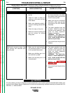
G1992 (Code 9402 only):
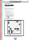
8. Turn OFF the machine
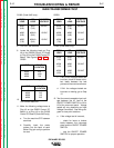
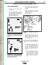
9. Locate the following leads on Plug
J6 on the G2252 Control PC Board
or Plug J3 on the G1992 Control PC
Board. See Figures F.1A & F1.B.
G2252:
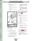
G1992 (Code 9402 only):
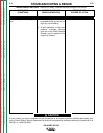
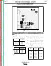
10.
Turn ON the machine.
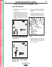
11. Make the following voltage tests at
Plug J6 on the G2252 Control PC
Board, or at Plug J3 on the G1992
Control PC Board (Code 9402 only.)
a. Turn the machine OFF between
each test.
b. Carefully insert the meter
probes into the back of each
Molex Plug pin cavity to perform
the test.
G2252:
G1992 (Code 9402 only):
c. If any of the voltages tested are
incorrect, check for loose or bro-
ken leads between the test
points and the main transformer.
d. If ALL the voltages tested are
incorrect or missing, go to Step
12.
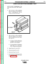
12. Test for correct nameplate input volt-
age between the H1 lead at the
ON/OFF POWER SWITCH to H2 or
H3 at the reconnect panel. Voltage
tested will vary depending on Input
Voltage Connection. See wiring dia-
gram for test point locations.
a. If the voltage test is incorrect,
- check for loose or broken
leads between the reconnect
panel and the ON/OFF POWER
SWITCH.
- test the ON/OFF POWER
SWITCH for proper operation.
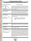
MAIN TRANSFORMER TEST
Return to Section TOC Return to Section TOC Return to Section TOC Return to Section TOC
Return to Master TOC Return to Master TOC Return to Master TOC Return to Master TOC
FROM
LEAD
#208
(16J6)
#208
(16J6)
#209
(7J6)
TO
LEAD
#209
(7J6)
#206
(4J6)
#206
(4J6)
EXPECTED
VOLTAGE
60 VAC
30 VAC
30 VAC
FROM
LEAD
#208
(1J3)
#208
(1J3)
#209
(2J3)
TO
LEAD
#209
(2J3)
#206
(3J3)
#206
(3J3)
EXPECTED
VOLTAGE
60 VAC
30 VAC
30 VAC
FROM
LEAD
#202
(6J3)
#202
(6J3)
#203
(7J3)
TO
LEAD
#203
(7J3)
#204 A
(5J3)
#204 A
(5J3)
EXPECTED
VOLTAGE
30 VAC
15 VAC
15 VAC
PLUG
LOCATION
4J6
16J6
7J6
LEAD
#206
#208
#209
PLUG
LOCATION
3J3
1J3
2J3
LEAD
#206
#208
#209