C-3
ACCESSORIES
C-3
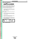
SPOOL GUN CONNECTION BOX
INSTALLATION
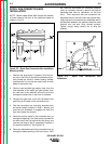
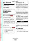
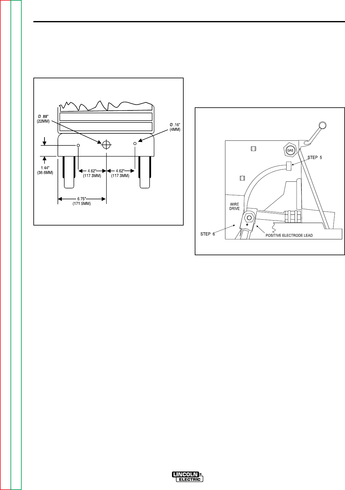
NOTE: Model codes below 9900 require the addition
of three holes to the front of the machine's base as
shown in Fig C.3.
Figure C.3 - Spool Gun Connection Box Installation
Mounting Holes
1. Remove the plug button, if present, from the cen-
ter hole in the front of the machine's base and par-
tially thread the two #10 thread forming screws,
provided with kit, into the two small holes on both
sides of the center hole.
2. Route a user-provided gas supply hose, from the
flow regulator of the spool gun gas cylinder, over
the rear axle of the machine, and out to the front
through the center hole in the front of the base.
3. Connect the gas hose to the 5/8-18 female inert
gas fitting on the back of the connection box.
4. Slip the connection box mounting keyholes over
the screw heads (installed in Step 1 above) and
pivot the box clockwise to engage and level the
box, then tighten the screws.
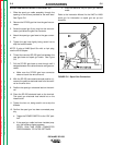
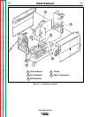
5. Route the control cable of the connection box up
through the opening in the front louver provided for
the work lead, then up behind the wire drive, and
connect the plug to the kit receptacle installed in
the previous section A. See Figure C.4.
6. Route the electrode lead of the connection box up
through the same opening in the front louver. With
the machine connected for electrode positive,
(refer to instruction manual), remove the positive
electrode lead from its connection on the wire
drive. Then reconnect with the connection box
electrode lead on the bolt under the positive elec-
trode lead so the connection box electrode lead is
sandwiched between the positive electrode lead
terminal and the wire drive contact surface.
Tighten snugly, being careful not to strip the
threads.
Figure C.4 - Spool Gun Connection Box
Installation.
IDEALARC SP-250
Return to Section TOC Return to Section TOC Return to Section TOC Return to Section TOC
Return to Master TOC Return to Master TOC Return to Master TOC Return to Master TOC


