


F-30
TROUBLESHOOTING & REPAIR
F-30
IDEALARC SP-250
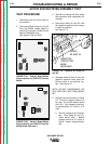
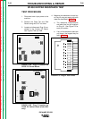
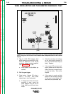
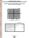
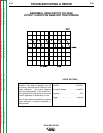
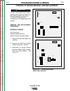
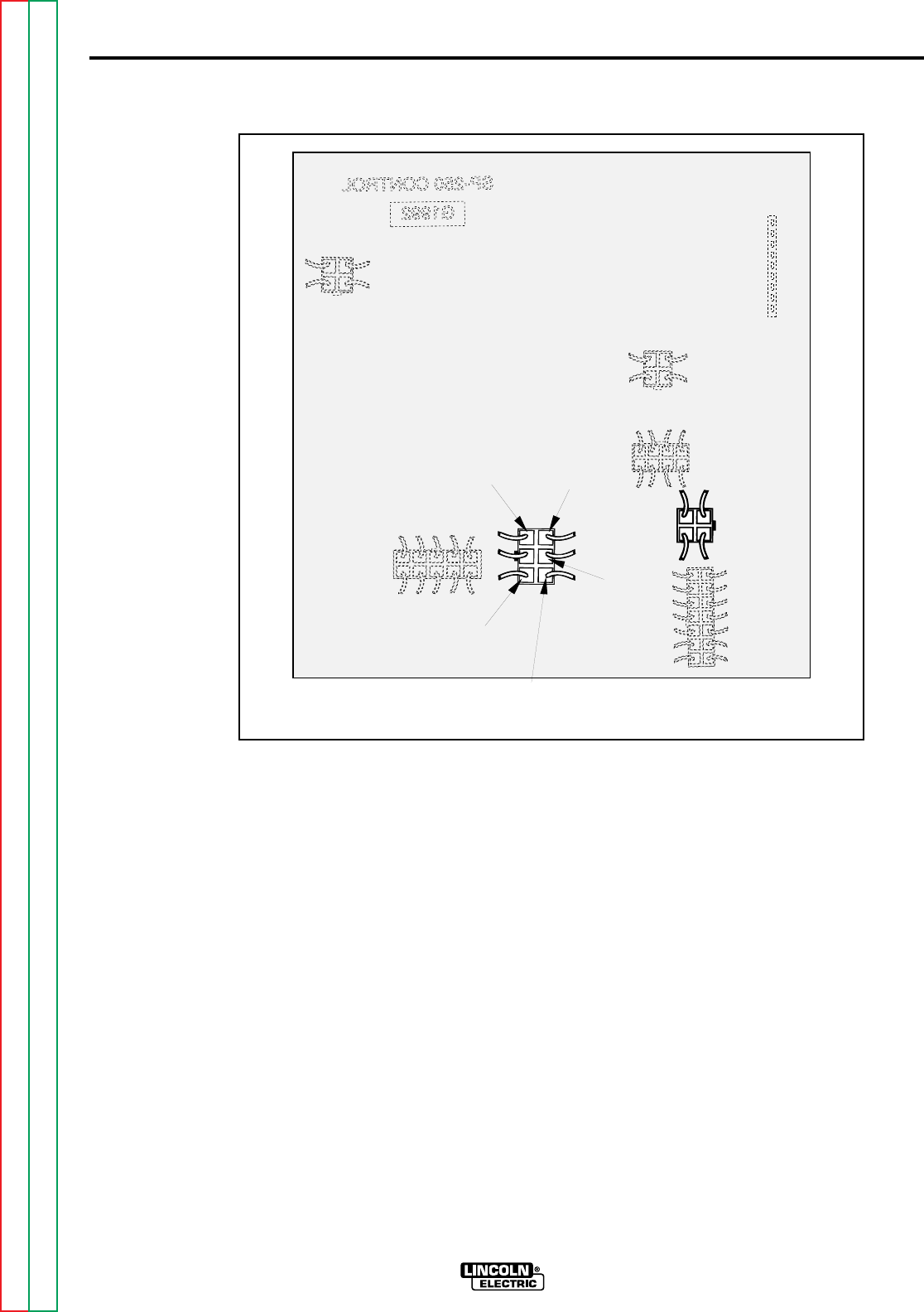
FIGURE F.10B - Plug J6 Location on G1992 PC Control Board (Code 9402 only.)
NOTE: Plugs J5 and J6 are on the inboard non-component side of the Control
Board.
4. Test for 2-25 VDC between lead
#539 (positive) and lead #541 (neg-
ative) to determine if the correct
armature voltage is being supplied.
See Figure F.10A or F.10B.
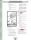
a. Insert probes in to the Molex pin
cavities.
5. Pull the gun trigger.
6. Read meter. Normal DC volts is
from 2 - 25 VDC. VDC varies
depending on wire feed speed.
a. If voltage to the wire drive motor
armature is zero, check the
wires between Plug J5 (J6 on
Code 9402) and the wire drive
motor.
b. If the wires are okay and voltage
to the drive motor armature is
zero, the Control Board may be
faulty. Replace.
c. If the correct DC armature volt-
age is present at the wire drive
motor, the motor or motor brush-
es may be faulty. Test and/or
replace.
d. If the motor is running at high
speed and the armature voltage
is high and uncontrollable, pro-
ceed with the tachometer test.
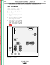
WIRE DRIVE MOTOR AND TACHOMETER FEEDBACK TEST
Return to Section TOC Return to Section TOC Return to Section TOC Return to Section TOC
Return to Master TOC Return to Master TOC Return to Master TOC Return to Master TOC
J2
J7
J4
J5
J3
J6
J9
J8
#541
(6J6)
#539
(3J6)
#206B
(4J6)
#555
(2J6)
#515B
(1J6)