


E-1
THEORY OF OPERATION
E-1
IDEALARC SP-250
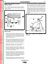
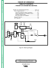
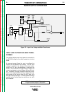
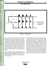
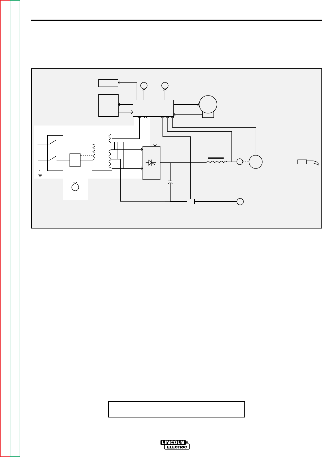
INPUT LINE VOLTAGE AND MAIN TRANS-
FORMER
The desired single phase input power is connected to
the SP-250 through a line switch located on the front
panel.
A reconnect panel allows the user to configure the
machine for the desired input voltage. This AC input
voltage is applied to the primary of the main trans-
former and to the thermostatically controlled fan
motors. The transformer changes the high voltage, low
current input power to a low voltage, high current out-
put. In addition, the main transformer also has an iso-
lated center tapped 30VAC auxiliary winding that sup-
plies power to the Control Board for SCR gate drive
and gas solenoid operation. The weld power windings
connect to the Control Board as well as to the main
SCR Rectifier.
Figure E.2 - Input Line Voltage and Main Transformer
POWER SUPPLY OPERATION
LINE
SWITCH
MAIN
TRANSFORMER
RECONNECT
FAN
MOTORS
SCR
RECTIFIER
C
A
P
A
C
I
T
O
R
S
SHUNT
CHOKE
WIRE
DRIVE
MOTOR
TACH
POSITIVE
TERMINAL
NEGATIVE
TERMINAL
GAS
SOLENOID
PIEZO
ALARM
KEYPAD
CONTROL BOARD
FEEDBACK
GUN TRIGGER AND THUMB SWITCH
F
E
E
D
B
A
C
K
G
A
T
E
I
G
N
S
A
L
LCD
DISPLAY
NOTE: Unshaded areas of Block Logic
Diagram are the subject of discussion
Return to Section TOC Return to Section TOC Return to Section TOC Return to Section TOC
Return to Master TOC Return to Master TOC Return to Master TOC Return to Master TOC