


INSTALLATION
A-5
LN-25™
A-5
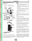
Install the barbed fitting and union nut to the
5
⁄8-18
female inert gas fitting on the front panel of the LN-
25™ case. Connect the
3
⁄16" I.D. gas hose from the gun
cable to the barbed fitting.
When the gun is to be removed, this fitting can be
easily detached by loosening the union nut.
WELD CABLE CONNECTION
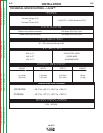
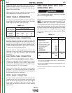
The size of the electrode cable and work cable must
be sufficient for the maximum weld current and total
cable length to be used. Refer to table A.1.
TABLE A.1
Total Cable Length
Weld Current
60% Duty Cycle 50'-100' 100'-150' 150'-200' 200'-250'
200Amps 2 AWG 2 AWG 1 AWG 1/0
300Amps 1 AWG 1 AWG 1/0 2/0
400Amps 2/0 2/0 3/0 3/0
500Amps 2/0 3/0 3/0 4/0
ELECTRODE CABLE CONNECTION
On units without an internal contactor route the
electrode cable through the oval hole in the LN-25™
rear panel, then along the case floor behind the reel
support and around the door side of the wire drive.
Connect the electrode cable to the LN-25™ using the
1⁄2" bolt on the front of the wire drive.
On units with an internal contactor connect the
electrode cable to the LN-25™ electrode input cable
with the nut and bolt provided. Tape the bolted
connection.
ELECTRODE CABLE CONNECTION
(FOR LATER CODE NUMBERS ABOVE 10500)
Route the electrode cable through the oval hole
in the lower portion of the LN-25™ rear panel.
Connect the electrode cable to the LN-25™ input
stud using the the 1/2” nut provided.
Secure the cable with the strain relief clamp
provided. All units are supplied with an optional
pigtail for customers that prefer to make a taped
and bolted connection externally.
WORK CABLE CONNECTION
Connect a work lead of sufficient size between the
proper output stud on the power source and the
work. Be sure the connection to the work makes
tight metal-to-metal electrical contact. Poor
work lead connections can result in poor welding
performance.
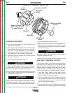
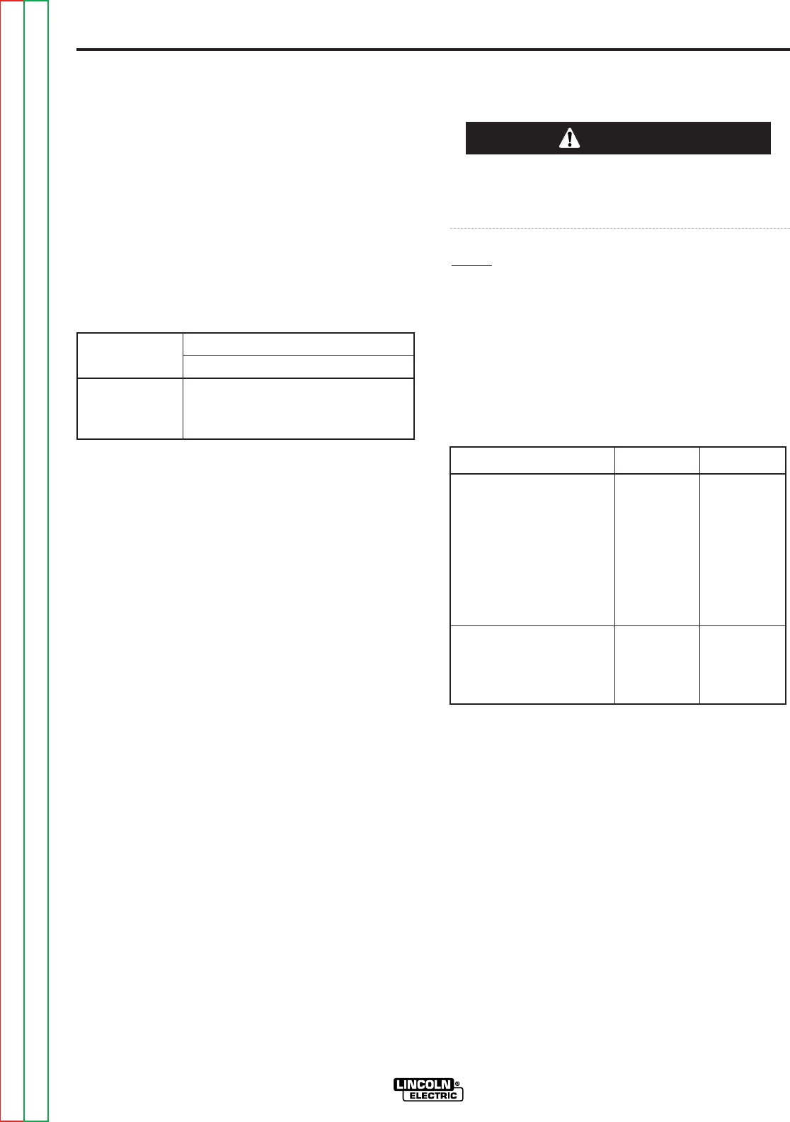
WIRE FEED DRIVE ROLL AND
GUIDE TUBE KITS
Turn off power source before installing or changing
drive roll and/or guide tubes.
NOTE: The maximum wire sizes the LN-25™ will
satisfactorily feed are
5
⁄64" cored and
1
⁄16" solid electrodes.
The electrode sizes that can be fed with each roll and
guide tube are stencilled
(1)
on each part. Check the kit
for proper components. See the instructions, included
with the drive roll kit, to install these parts on new
machines or replace them on used machines. Refer
to table A.2.
TABLE A.2
Kit Instructions
Steel Wire Sizes:
.068-
5
⁄64 Cored KP653-
3
⁄32 L9932
1
⁄16 (.062) Cored or Solid -
1
⁄16
Steel
(Can also be used for .052)
.045 and .052 Solid Steel -.052
.045 and .052 Cored -.052C
.035 Solid Steel -.035S
.035 Cored -.035C
.030 Solid Steel -.030S
.025 Solid Steel -.025S
Aluminum Wire Sizes:
1
⁄16 KP654-
1
⁄16A L9932
3
⁄64 -
3
⁄64A
.035 -.035A
(1)
Drive rolls for only cored electrode sizes are stencilled with a
“C” suffix to the wire sizes.
Drive rolls for only solid electrode sizes are stencilled with an “S”
suffix to the wire sizes.
Drive rolls for aluminum wire sizes are stencilled with an “A” suffix
to the wire sizes.
WARNING
Return to Section TOC Return to Section TOC Return to Section TOC Return to Section TOC
Return to Master TOC Return to Master TOC Return to Master TOC Return to Master TOC