


Return to Section TOC Return to Section TOC Return to Section TOC Return to Section TOC
Return to Master TOC Return to Master TOC Return to Master TOC Return to Master TOC
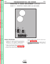
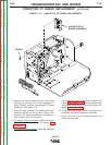
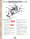
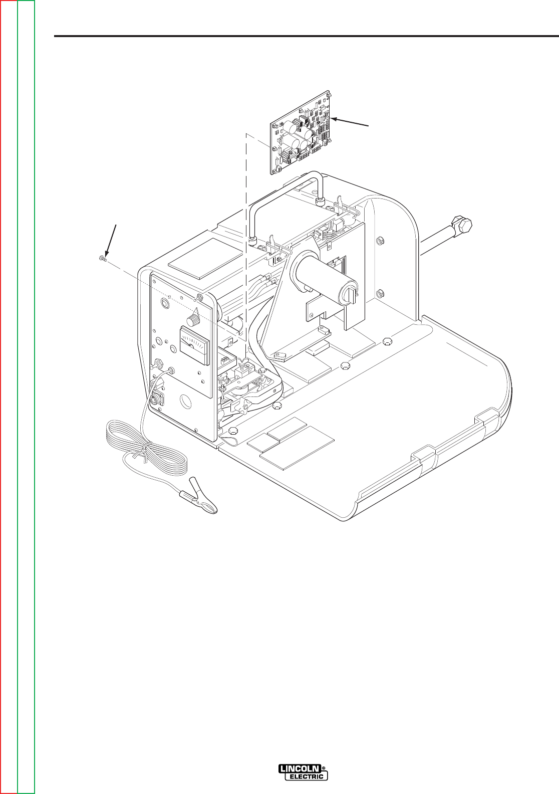
7. Remove the screws holding the control PC
board to the inside of the case. Carefully
remove the control board. See Figure F.24.
8. Place the new control PC board in position
inside the case. Secure the control PC board
by installing the screws from the outside of the
case.
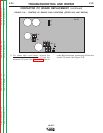
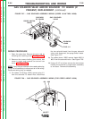
9. For codes 10148 and above, install the four
Molex type plugs J1, J2, J3 and J4 onto the
control PC board. See Figure F.20.
NOTE:For Codes above 10148 with a newer
Control Board (L12253-[ ]) and a contactor,
install plug J14. See Figure F.22.
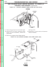
10. For codes 9812 and below, install the four
Molex type plugs J1, J2, J3 and J4. Also,
connect the five individual leads to the control
PC board. If necessary, refer to the wiring
diagrams in the Electrical Diagrams Section.
See Figure F.21.
11. Re-install the Contactor PC Board or Remote
Control PC Board if previously removed
11. Install the control box cover and secure by
installing the screws previously removed.
12. Install the wire reel and retaining collar and
close the case door.
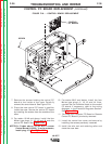
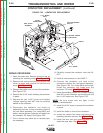
CONTROL PC BOARD REPLACEMENT (continued)
FIGURE F.24. – CONTROL BOARD REPLACEMENT.
TROUBLESHOOTING AND REPAIR
F-38
F-38
LN-25™
SCREW
CONTROL
PC BOARD